


Service 17
MAN0003 (Rev. 11/30/2006)
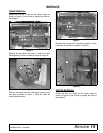
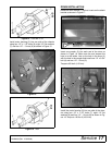
Figure 14. TL52 and TL73
Install motor housing (5) into one side of the chassis
using four 1/2” x 1-1/2” bolts (6), eight 1/2” flat washers
(7) and four 1/2” - 13 nuts (8) as shown in Figure 15.
Figure 15.
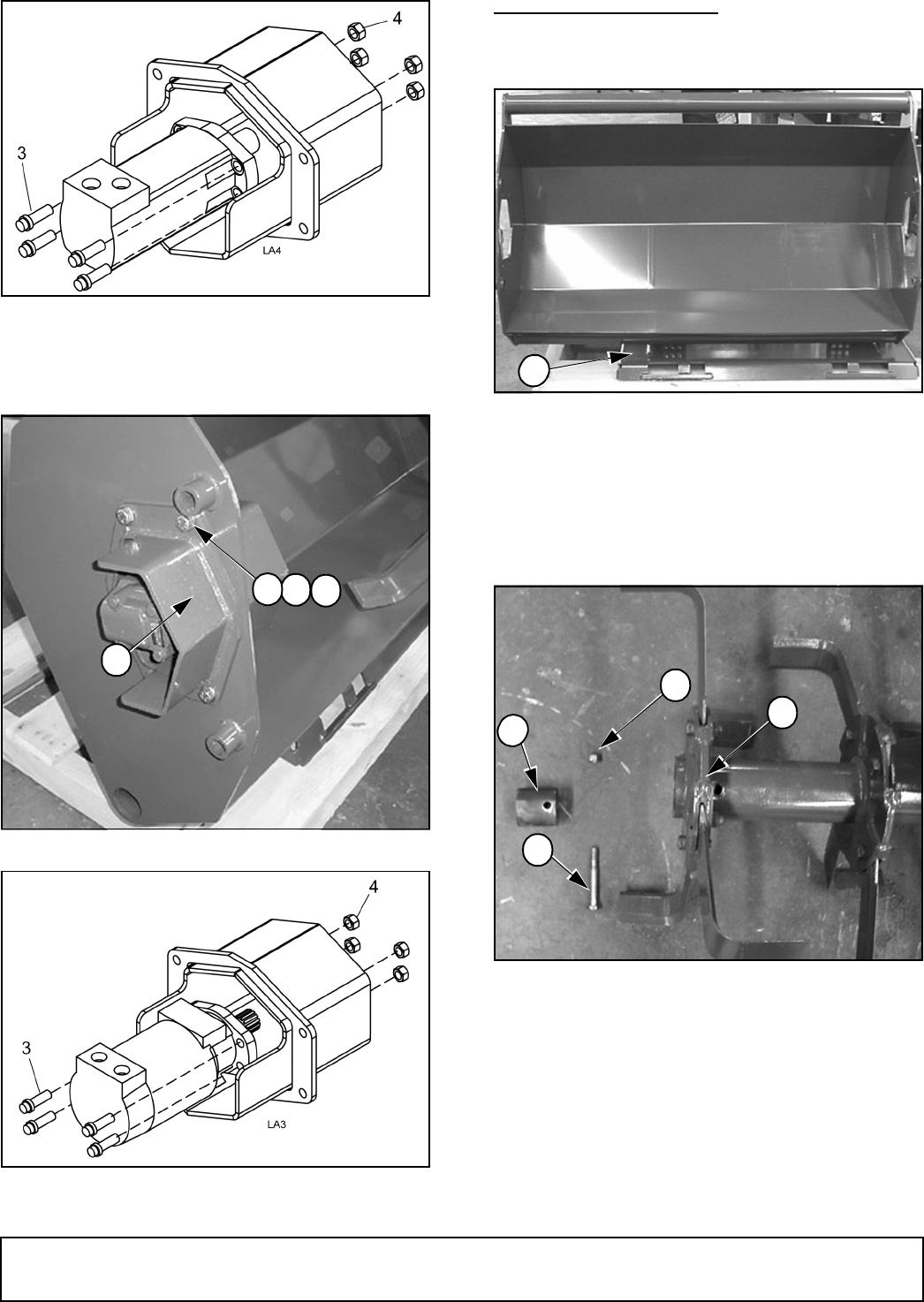
Figure 16. TL84
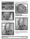
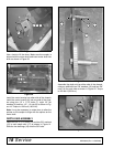
DRUM INSTALLATION
Rotate the tiller chassis (1) so that it rests on the attach
bracket as shown in Figure 17.
Figure 17.
Insert one coupler (2) into each end of the drum as
shown in Figure 18. Make sure the end nearest the
hole is to the inside. Line up the hole in the drum (3)
with the hole in the coupler and install one 1/2" x 3-3/4"
bolt (4) and one 1/2" - 20 nut (5).
Torque to 85 lbs-ft (115 N-m).
Figure 18.
Install the motor housing (6) into one side of the chas-
sis using four 1/2" x 1-1/2" bolts (7), eight 1/2" flat
washers (8) and four 1/2" - 13 nuts (9) as shown in Fig-
ure 19. Torque to 120 lbs-ft (163 N-m).
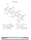
DP10
5
6
7
8
1
DP12
5
3
4
2
DP7