


Assembly 9
12030809 (Rev. 1/2/2007)
ASSEMBLY
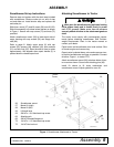
Snowthrower Set-up Instructions
Remove step and replace with the short step included
with snowthrower. Remove cotter pin on end of step
rod and slide out. Install shorter step and replace rod
and cotter pin.
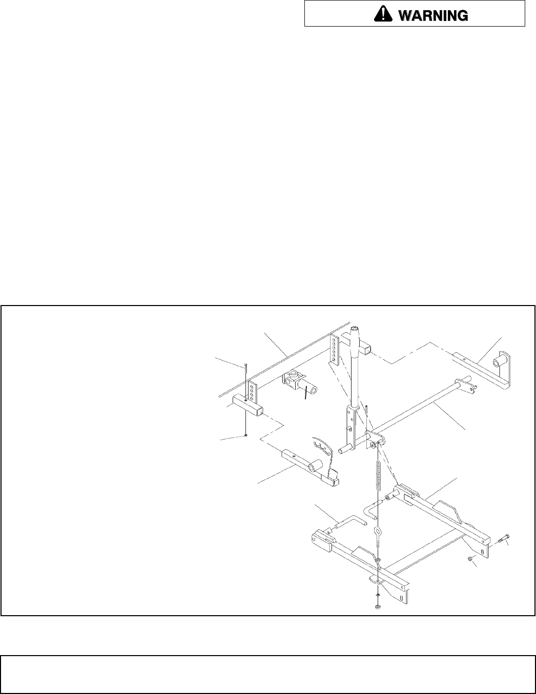
Slide lever mount (27) and lift mount (28) onto lift (29).
Slide this assembly into tubes below footrest as shown
in Figure 1. Secure with cap screws (73) and nuts (75)
provided.
Attach snowthrower mount (26) to lower back side of
auger housing with cap screws (59) and flange lock-
nuts (69).
Refer to page 12. Attach upper spout (2) with cap
screws (50), spacers (48), washers (49), lock washers
(51) and hex nuts (52). Spout should be free to rotate
approximately 180 degrees when spout handle (5) is
pushed down to release spout lock.
Attaching Snowthrower to Tractor
Make sure the driveline spring-activated locking
collar slides freely and is seated firmly in power
unit PTO groove. Make sure the set screws
securely attach driveline to the attachment gearbox
shaft.
The tractor must comply with counterweight require-
ments before attaching snowthrower. See Counter-
weight Requirement Chart in the tractor manual or
contact your dealer.
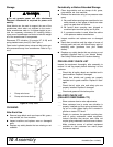
Place tractor and snowthrower on a level surface. Shut
off tractor engine and remove key.
Open tractor hydrostat dump valve and maneuver trac-
tor behind snowthrower as close as possible. Connect
driveline, Figure 1, to tractor PTO.
Attach snowthrower mount (26) to bottom holes of trac-
tor mount as shown. Secure with attaching pins (63).
Install lift chains to lift chain mechanism and
snowthrower mount. Adjust eyebolt for even lift.
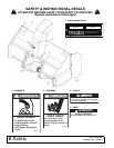
Figure 1. Snowthrower Attachment to Tractor
73
75
PTO
27
63
28
29
26
69
59
CD00218011
Tractor
Frame
26. Snowthrower mount
27. Mount lift (right)
28. Mount lift (left)
29. Lift hand lever
59. 3/8 NC x 1-3/4 Hex head cap screw
63. Attaching pin
69. 3/8 NC Serrated flange nut
73. 1/4 NC x 1-1/2 Hex head cap screw
75. 1/4 NC Hex lock nut