


Assembly 29
MAN0180 (Rev. 1/7/2005)
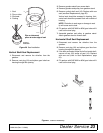
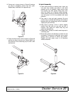
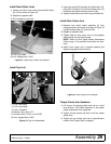
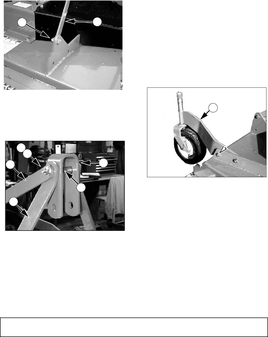
Install Rear Offset Links
1. Loosen nut (56) at rear frame lug and attach offset
link (13) as shown in Figure 33.
2. Repeat for opposite side.
3. Do not tighten at this time.
Figure 33. Right Rear Offset Link Installed
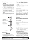
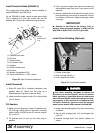
Install Top Link
Figure 34. Top Link Assembled
1. Insert cap screw (54) through rear offset links (13),
pipe (49), U-bracket (15) and front offset links (14)
as shown and tighten securely with nut (56).
2. Tighten hardware on rear frame lug and offset link.
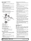
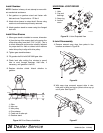
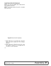
Install Rear Caster Arm
1. Remove rear caster wheel assembly (3) from
shipping position and install as shown in Figure 35
using the same bolts (51) and nuts (56).
2. Repeat for opposite side.
3. Tighten bolts so that caster arm is snug against
deck bracket, but not fully torqued.
NOTE: Refer to Front Caster Wheel Interference
Check, page 11 for possible front caster arm posi-
tions.
4. Attach front caster arm in desired position and
tighten snug against deck bracket.
Figure 35. Rear Caster Arm Installed
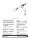
Torque Caster Arm Hardware
1. Lift mower off shipping pallet and set on a hard
level surface. This allows clearance in the caster
wheel assemblies to be equalized.
2. Tighten all cap screws and nuts on all four caster
wheel arms.
3. Tighten all cap screws and nuts to specifications
found in Bolt Torque Chart on page 41.
CM905
56
13
13. Link, rear offset
56. Nut, flanged lock 1/2 NC
49
15
14
56
54
13
CM757
1
3
.
L
i
n
k
,
r
e
a
r
o
f
f
s
e
t
1
4
.
L
i
n
k
,
f
r
o
n
t
o
f
f
s
e
t
1
5
.
L
i
n
k
,
U
-
b
r
a
c
k
e
t
4
9
.
S
l
e
e
v
e
,
.
6
2
x
.
8
4
x
2
.
7
5
5
4
.
S
c
r
e
w
,
H
H
C
S
1
/
2
N
C
x
4
-
3
/
4
G
R
5
5
6
.
N
u
t
,
f
l
a
n
g
e
d
l
o
c
k
1
/
2
N
C
3