


10 Operation
MAN0180 (Rev. 1/7/2005)
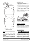
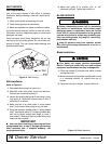
Figure 5. Height Adjustment with Caster Arm Spacers
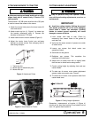
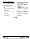
TRACTOR TOP LINK ADJUSTMENT
When the cutting height is set, adjust tractor top link
until mower top link attachment point A is aligned verti-
cally with mower hitch pin B.
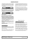
Adjust tractor top link so mower is level between caster
wheel and ground (dimension C Figure 7). This will
allow the mower to follow ground contour.
Figure 6. Top Link Adjustment
Figure 7. Gauge Wheel Distance
FRONT CASTER ARM CONFIGURATION
For RD6000-2 & RD7200-2 only
The RD6000-2 and RD7200-2 front casters can be set
in two positions using the right and left offset caster
arms. Figure 8 shows a right offset assembly.
Check the offset position by looking from mounting
hole A to pivot tube B. The pivot tube should be higher
than the mounting holes.
Figure 8 shows the two possible configurations for the
RD6000-2 and RD7200-2 front caster arms.
● The inner position allows the outside edge of the
mower to be used for trimming under shrubs or
fences.
● The outer position provides the most clearance for
rear tractor tire interference.
To change configurations, remove the cap screws and
nuts and move the arms from one side of the machine
to the other. Secure with hardware.
The rear caster arms should be mounted as shown.
NOTE: The RD8400-2 front caster arms are fixed and
cannot be changed.
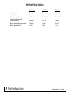
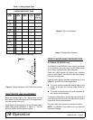
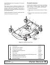
Table 1: Cutting Height Chart
SPACERS REQUIRED UNDER
CASTER ARM PIVOT TUBE
Cut
Height
1/2"
Spacer
3/4"
Spacer
1"
Space
r
1-1/4"
*Spacer
(Spring)
1"
1-1/2" 1
2" 1
2-1/2" 11
3" 2
3-1/2" 12
4" *111
4-1/4" 112
4-1/2" *1 1 1 1
5" *121
5-1/2" *1 1 2 1
* RD6000 and RD7200 only