


22 Assembly
MAN0253 (Rev. 3/10/2007)
ASSEMBLY INSTRUCTIONS
DEALER SET-UP INSTRUCTIONS
Assembly of this mower is the responsibility of the
Woods dealer. It should be delivered to the owner com-
pletely assembled, lubricated, and adjusted for normal
cutting conditions.
The mower is shipped partially assembled. Assembly
will be easier if components are aligned and loosely
assembled before tightening hardware. Recommended
torque values for hardware are located on page 47.
Select a suitable working area. A smooth, hard, level
surface, such as concrete, will make assembly much
quicker.
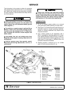
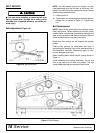
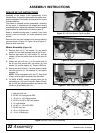
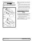
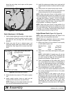
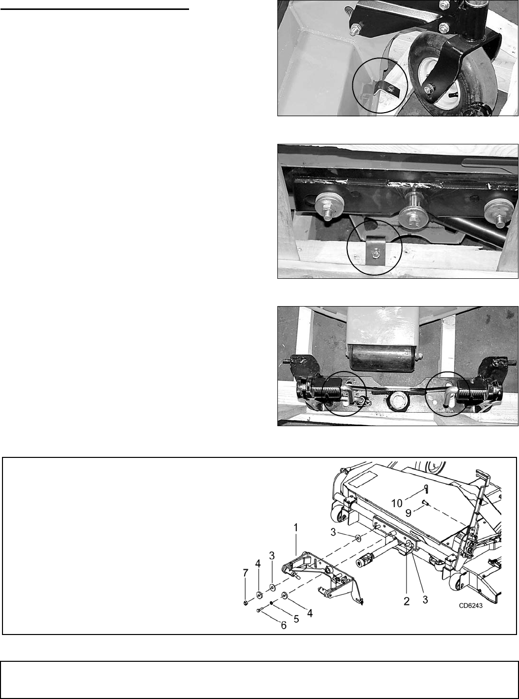
Remove front and rear hardware that secures deck to
crate as shown in Figure 15, Figure 16, and Figure 17.
Remove deck from crate.
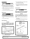
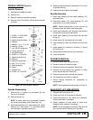
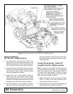
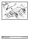
Mower Assembly (Figure 18)
1. Remove lock nut (7), flat washer (4), and plastic
washer (3) from both carriage bolts on the lift arm.
2. Remove cap screw (6), lock washer (5), and flat
washer (4) from the center hub on the rear pivot lift
arm (1).
3. Attach rear pivot lift arm (1) to the center hub on
the lift arm and secure with cap screw (6), lock
washer (5), and flat washer (4). Torque to 85 lbs-ft.
4. Secure rear pivot lift arm (1) on both sides of center
hub with lock nuts (7), flat washers (4), and plastic
washers (3).
NOTE: Do not overtighten lock nuts (7). Rear pivot
lift arm must be tight but should pivot with effort.
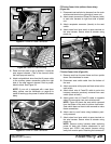
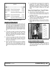
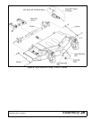
5. On MX54 & MX61 models, remove clevis pin (9)
and safety pin (10) from lift handle. Rotate lift han-
dle up into the operating position and secure with
clevis pin (9) and safety pin (10).
Figure 15. Left Front Corner Clip & Lag Bolt
Figure 16. Rear Clip & Lag Bolt
Figure 17. Rear Pivot Lift Arm Lag Bolts
Figure 18. Rear Pivot Lift Arm Assembly
DP1
DP2
DP3
1. Rear pivot lift arm
2. 5/8 NC x 2 Carriage bolt GR5
3. .53 x 2.0 x .125 Plastic washer
4. 5/8 ID x 2.0 OD x 3/8 Thick washer
5. 1/2 Lock washer
6. 1/2 NC x 1-1/2 HHCS GR5
7. 5/8 NC Lock nut
9. .62 x 1.50 Clevis pin
10. .19 x 3.16 Safety pin