


Service 19
MAN0253 (Rev. 3/10/2007)
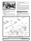
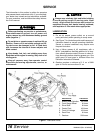
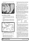
SPINDLE REPAIR (Figure 12)
Spindle Removal
1. Remove belt shields from deck.
2. Remove belt.
3. Remove blade from spindle assembly.
4. Remove nuts (7) and bolts (10) that secure spindle
to mower.
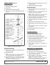
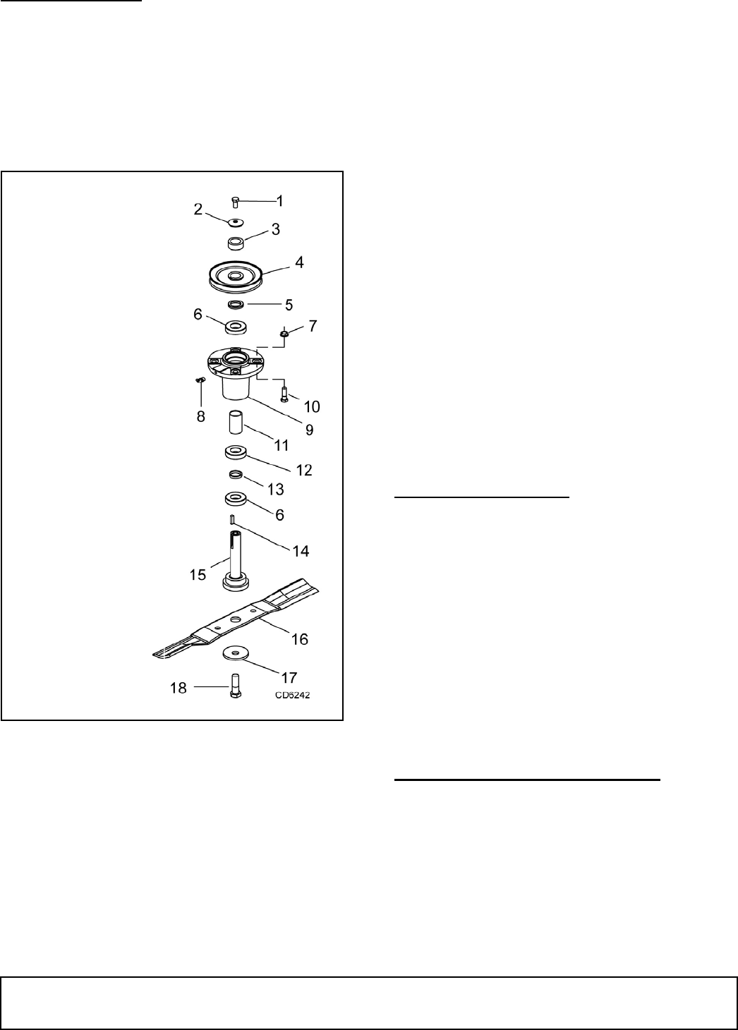
Figure 12. Blade Spindle Assembly
Spindle Disassembly
1. Remove bolt (1), washer (2), and spacer (3) from
the top of the spindle.
2. Remove sheave (4).
NOTE: A wheel puller may be needed if sheave
can not be removed by hand. Retain key (14).
3. Slide shaft assembly (15), lower bearing (6), center
bearing (12), long spacer (11), and short spacer
out the bottom of spindle housing (9).
4. Remove upper bearing (6) and spacer (5) from top
of spindle housing.
5. Inspect parts and replace as needed.
Spindle Assembly
1. Slide lower bearing (6) over shaft assembly (15)
with seal down.
2. Slide short spacer (13), center bearing (12), and
long spacer (11) on shaft assembly.
NOTE: Center bearing has no seal and can be
placed on shaft with either side facing down.
3. Insert shaft assembly with bearings and spacers
into spindle housing from the bottom.
4. Install upper bearing (6) over shaft with the seal
facing up.
5. Install spacer (5) and sheave (4) over shaft.
6. Align keyways in shaft and sheave and insert key
(14).
7. Install spacer (3), washer (2), and bolt (1). Torque
bolt to 35 lbs-ft.
8. Rotate sheave and check for free movement.
9. Lubricate spindle.
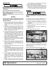
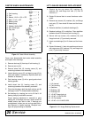
GEARBOX REMOVAL
1. Remove mower deck from power unit.
2. Remove center belt shield and belt.
3. Remove driveline from gearbox. Retain key.
4. Remove bolt and sheave from gearbox. A wheel
puller may be required. Retain key.
5. Remove the two bolts mounting the gearbox.
6. Lift out gearbox and repair or replace.
7. Follow reverse procedure for reassembly or
replacement.
NOTE: Torque gearbox mounting bolts to 35 lbs-ft.
REAR PIVOT LIFT ARM SERVICE
1. Remove deck from power unit.
2. Check rear pivot lift for excessive free play.
3. Check the torque on the center hub hardware.
Torque to 85 lbs-ft if necessary.
4. Check hardware on both sides of center hub.
Replace plastic washers if necessary.
NOTE: Do not overtighten hardware. Rear pivot lift
arm must be tight but should pivot with effort.
1. 3/8 NF x 1 HHCS GR5
2. Washer, cupped
3. Spacer, spindle sheave
4. Sheave
5. Spacer, 1.01 x 1.51 x .25
6. Bearing, .25 mm
7. Nut, 3/8 NC flange lock
8. Fitting, grease 45°
9. Spindle housing
10. 3/8 NC x 1-1/2 HHCS
11. Spacer, spindle long
12. Bearing
13. Spacer, spindle short
14 Key, .25 x .25 x .69
15. Shaft assembly
16. Blade
17. Washer, bell
18. 5/8 NF x 2-1/2 HHCS