14 Operation
MAN0670 (11/16/2007)
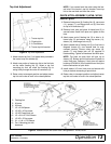
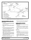
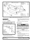
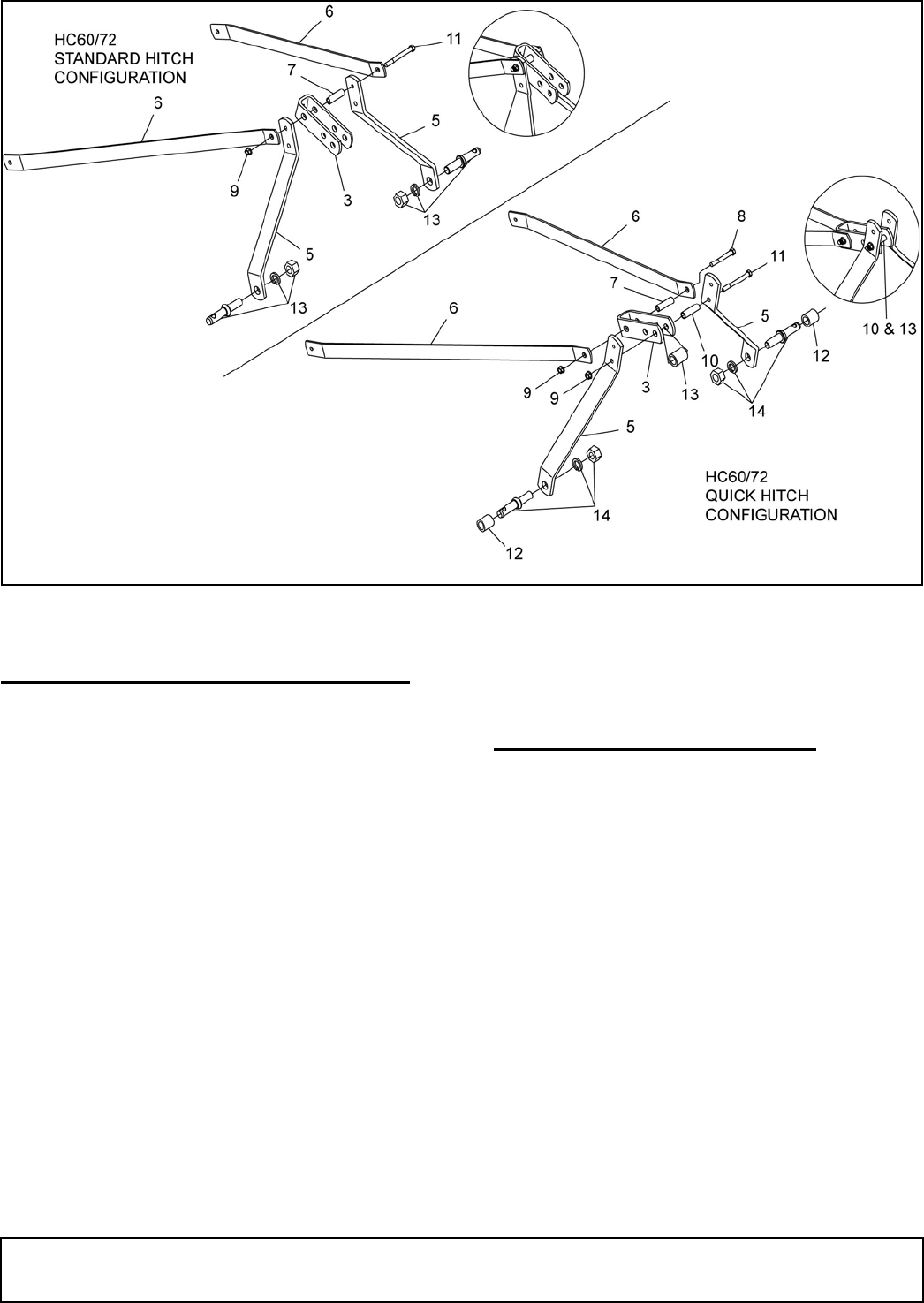
Figure 4. Standard Hitch and Quick Hitch Configurations - HC60, HC72
QUICK HITCH ASSEMBLY (HC60 / HC72)
Refer to Figure 4.
1. Remove brace arms (6), floating link (3), cap screw
(11), spacer (7), and flange lock nut (9) from upper
hole on A-frame bars (5).
2. Remove hitch pins and place sleeves in hole of
diagonal braces. Install hitch pins and tighten at
this time.
3. Attach open end of floating link (3) to second hole
on top of A-frame bars (5). Secure using cap screw
(11), sleeve (10), and flange lock nut (9).
4. Attach closed end of floating link (3) to diagonal
braces (6). Secure using cap screw (8), spacer (7),
and flange lock nut (9) supplied in hardware bag.
Tighten all hardware and hitch pins.
NOTE: Top hook on quick hitch will pick up on
sleeve (10). Bottom quick hitch hooks will attach to
cutter hitch pins. Category I hitch pins will require
bushings (PN 38214) to be installed over hitch pins
before connection to quick hitch.
5. Install sleeve (12) over hitch pins and secure with
klick pin before connecting to quick hitch.
6. Raise cutter to transport position and adjust tractor
top link until cutter is level in the raised position.
ATTACH CUTTER TO TRACTOR
Standard Hitch
1. Attach tractor 3-point arms to hitch pins and secure
with klik pins.
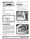
2. Attach tractor top link to the floating link and adjust
as necessary. See Top Link Adjustment, page 13.
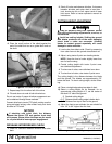
3. Adjust the tractor lower 3-point arm anti-sway
devices to prevent cutter from swinging side to
side.
Quick Hitch
1. Attach tractor 3-point arms to hitch pins and secure
with klik pins.
2. Attach tractor with the quick hitch to the cutter and
secure according to the quick hitch manufacturer's
instructions. Adjust tractor top link as necessary.
See Top Link Adjustment, page 13.
3. Adjust the tractor lower 3-point arm anti-sway
devices to prevent cutter from swinging side to
side.
3. Floating link
5. A-frame
6. Lift bars
7. 1/2 x 2-3/4 Spacer
8. 1/2 NC x 4 Cap screw
9. 1/2 NC Flange lock nut
10. 1/2 x 3/4 x 2-13/16 Sleeve
11. 1/2 NC x 5 Cap screw
12. .91 x 1.44 x 1.25 Sleeve
13. Cat 1 Mounting pin with hardware
(Rev. 5/9/2008)


