40 Assembly
MAN0764 (11/5/2008)
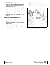
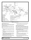
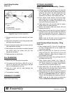
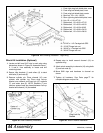
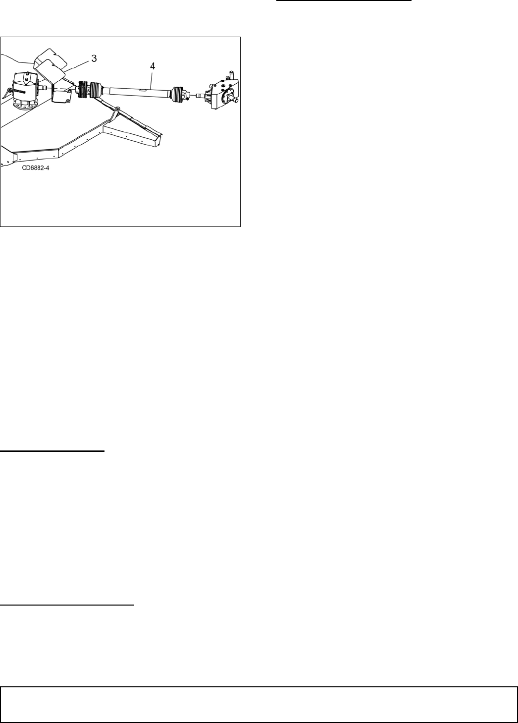
Install Wing Driveline
(Figure 33)
Figure 33. Right Driveline Installation
1. Remove knob on top of clutch shield (3) and raise
shield.
2. Slide clutch of driveline (4) over wing gearbox shaft
and align holes with groove.
3. Secure driveline to shaft using cap screws and lock
nuts supplied with driveline.
4. Slide opposite end of driveline over splitter gearbox
and secure using cap screws and lock nuts
supplied with driveline.
5. Repeat process for left driveline.
FILL GEARBOXES
1. Remove top and side plugs from gearbox.
2. Fill gearbox with SAE 80W or 90W EP oil until it
runs out of side level hole. Install plug in the side
hole and vented dipstick in the top.
3. Allow oil to drain into the lower bearings and
recheck oil level.
4. Fill gearboxes if needed.
HYDRAULIC CYLINDER
Attach hose to each elbow.
OPTIONAL EQUIPMENT
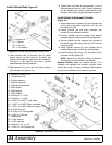
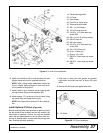
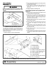
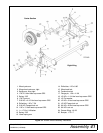
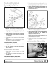
Install Tandem Wheel Assembly - Center
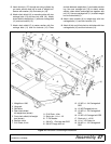
(Figure 34)
1. Slide spring wheel arm assembly (1) over right side
of center wheel yoke tube and secure into position
using four cap screws (22) and flanged lock nuts
(23). Repeat step to install spring wheel arm
assembly on left side of center wheel yoke tube.
2. Place tandem wheel bracket (16) around lower
lower spring arm (13) and insert flange pin (17).
Secure flange pin to tandem wheel bracket using
cap screw (18) and flat washer (19).
3. Insert wheel hubs (15) into both sides of tandem
wheel bracket (16) and align holes.
4. Secure into position using cap screws (20) and
flanged lock nuts (21).
5. Attach wheel to hub using five lug nuts. Install the
chamfered side of the lug nut toward the inside for
steel rim for pneumatic tires and rims. Tighten to 75
lbs-ft. Check that tire air pressure is a maximum of
40 psi.
NOTE: Install the flat side of the nut toward the
inside for solid tires and aircraft tires (shown)
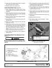
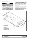
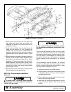
Install Tandem Wheel Assembly - Wing
(Figure 34)
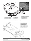
1. Place carriage bolt (67), Figure 32, through holes
on wing. Carriage bolts are on the outside; lock
nuts on the underside.
2. Attach wing wheel yoke (2), Figure 34, to the wing
using pivot pins (31). See Figure 32 for pin and
hardware installation. Make sure pin flange is on
the underside of the deck.
3. Secure pivot pins to deck using carriage bolts (67)
and flange lock nuts (53).
4. Place tandem wheel bracket (16), Figure 34,
around lower spring arm (3) and insert flange pin
(17). Secure flange pin to tandem wheel bracket
using cap screw (18) and flat washer (19).
5. Insert wheel hubs (15) into both sides of tandem
wheel bracket (16) and align holes. Secure using
cap screws (20) and flanged lock nuts (21).
6. Attach wheel to hub using five lug nuts. Install the
chamfered side of the lug nut toward the inside for
steel rim for pneumatic tires and rims. Tighten to
75 lbs-ft. Set tire pressure to a maximum of 40 psi.
NOTE: Install the flat side of the nut toward the
inside for solid tires and aircraft tires (shown).
3. Clutch shield
4. Wing driveline, complete


