Assembly 39
MAN0764 (11/5/2008)
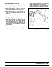
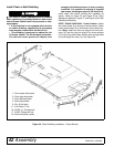
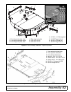
8. Insert hose (25) through hose guide on transport
lock bracket and secure to elbow.
9. Repeat procedure for opposite wing.
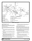
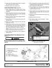
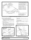
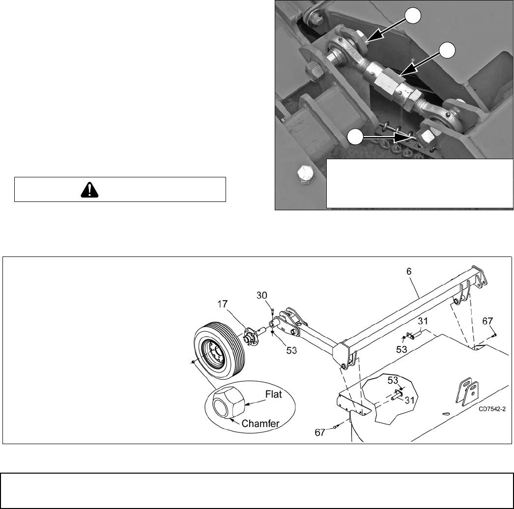
Install Wing Wheel Yoke (Figure 32)
1. Place carriage bolts (67) through holes in wing.
Carriage bolts are on the outside; lock nuts on the
underside.
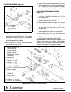
2. Attach wing wheel yoke (6) to the wing using pivot
pins (31). Make sure pin flange is on the underside
of the deck. See Figure 32.
3. Secure pivot pins to deck using carriage bolts (67)
and flange lock nuts (53).
4. Insert wheel hub (17) into wing wheel yoke arm (6)
and align holes.
5. Secure into position using cap screw (30) and
flanged lock nut (53).
6. Attach wheel to hub using five lug nuts. Install the
chamfered side of the lug nut toward the inside for
steel rim for pneumatic tires and rims. Tighten to 75
lbs-ft. Set tire pressure to a maximum of 40 psi.
NOTE: Install the flat side of the nut toward the
inside for solid tires and aircraft tires (shown).
7. Install optional dual wheel and hub to inside of
wheel yoke arm.
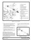
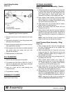
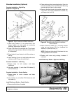
Install Wing Wheel Yoke Adjustment Link
(Figure 31)
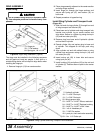
Use a suitable lifting device of sufficient capac-
ity. Use adequate personnel to handle heavy com-
ponents.
1. With a lifting device raise right wing and lock in the
up position using the wing lock-up bar. Leave lifting
device attached for added support.
2. Attach adjustable link (turnbuckle, 22) to right side
of center wheel yoke arm and secure with cap
screw (32) and lock nut (26).
3. Attach opposite end of adjustable link (22) to wing
wheel yoke arm and secure with cap screw (32)
and lock nut (26).
4. Remove lock-up bar and carefully lower wing using
lifting device.
5. Repeat process for left wing.
6. See Cutting Height (Normal Mowing) - Wings,
page 16 to level wings.
Figure 31. Right Wing Wheel Yoke;
Adjustment Link Installed
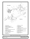
Figure 32. Wing Wheel and Hub Installation - Right
CAUTION
32
DP6
22. Adjustable link
26. 1 NC Lock nut
32. 1 NC x 4 Hex head cap screw GR8
22
26
6. Wing wheel yoke arm, right
17. Wheel and hub
30. 1/2 NC x 3 Hex head cap
screw GR5
31. Pivot pin, 1-1/4
53. 1/2 NC Flanged lock nut
67. 1/2 NC x 1-1/2 Carriage bolt


