Operation 13
MAN0680 (11/30/2007)
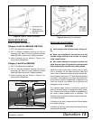
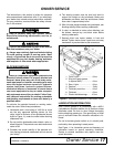
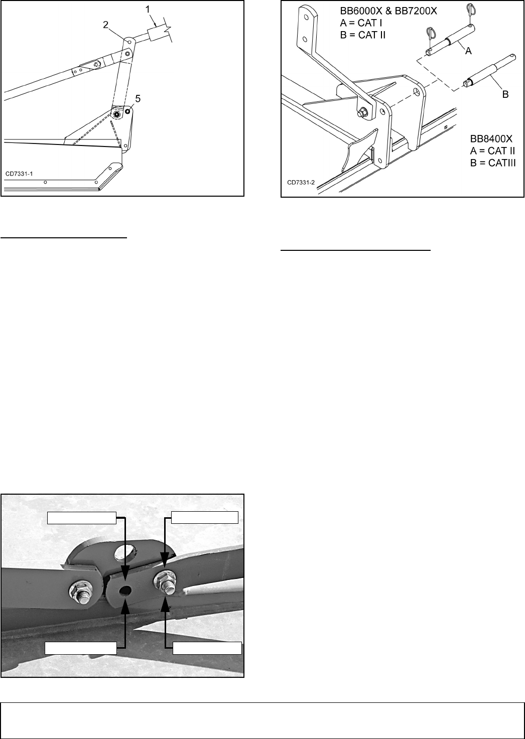
Figure 2. Cutter to Tractor Connection
QUICK HITCH SET-UP
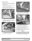
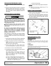
Refer to Figure 3 and Figure 4.
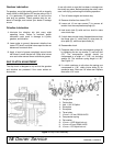
Category I and II for BB6000X, BB7200X
1. CAT I: No adjustment is required.
2. CAT II: Remove hardware securing lift arms to
mounting lugs. Move lift arms forward to second
holes and insert caps screws. Tighten hardware.
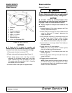
3. Install mounting pins as shown in Figure 4 for
correct hitch configuration.
Category II and III for BB8400X
1. CAT II: No adjustment is required.
2. CAT III: Remove hardware securing lift arms to
mounting lugs. Move lift arms forward to second
holes and insert cap screws. Tighten hardware.
3. Install mounting pins as shown in Figure 4 for
correct hitch configuration.
Figure 3. Left Rail Mounting Lug
Figure 4. Mounting Pin Installation
DRIVELINE ADJUSTMENT
NOTICE
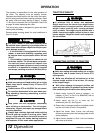
■ Avoid contact with driveline when raising cut-
ter.
■ Make sure driveline will not bottom out at the
shortest length and that it has at least 1/3 overlap
at the longest length.
■ With cutter adjusted to transport position, set
upper stop on tractor lift quadrant to prevent cutter
from contacting the driveline when being raised.
Attach the cutter to the tractor 3-point hitch (or quick
hitch if available). Do not attach driveline. Raise and
lower cutter to determine maximum and minimum dis-
tance between the tractor PTO shaft and the gearbox
input shaft. If the distance is too large, the driveline will
be too short for proper engagement. If distance is too
small, the driveline may bottom out in operation and
damage the cutter or tractor.
The driveline length must be sufficient to provide at
least 1/3 driveline length of engagement during opera-
tion. There must be at least 4 inches of engagement at
the cutter’s lowest possible point of operation. The
driveline must not bottom out when raised to the maxi-
mum height possible.
If driveline is too short, please call your Woods dealer
for a longer driveline.
If driveline is too long, please follow the instructions for
shortening the driveline.
1. Tractor top link
2. Cutter top link
attachment point
5. Hitch pin
BB6000X, BB7200X
BB8400X
CAT II Position
CAT I Position
CAT II Position
CAT III Position


