12 Assembly
29929 (Rev. 3/28/2008)
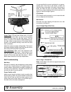
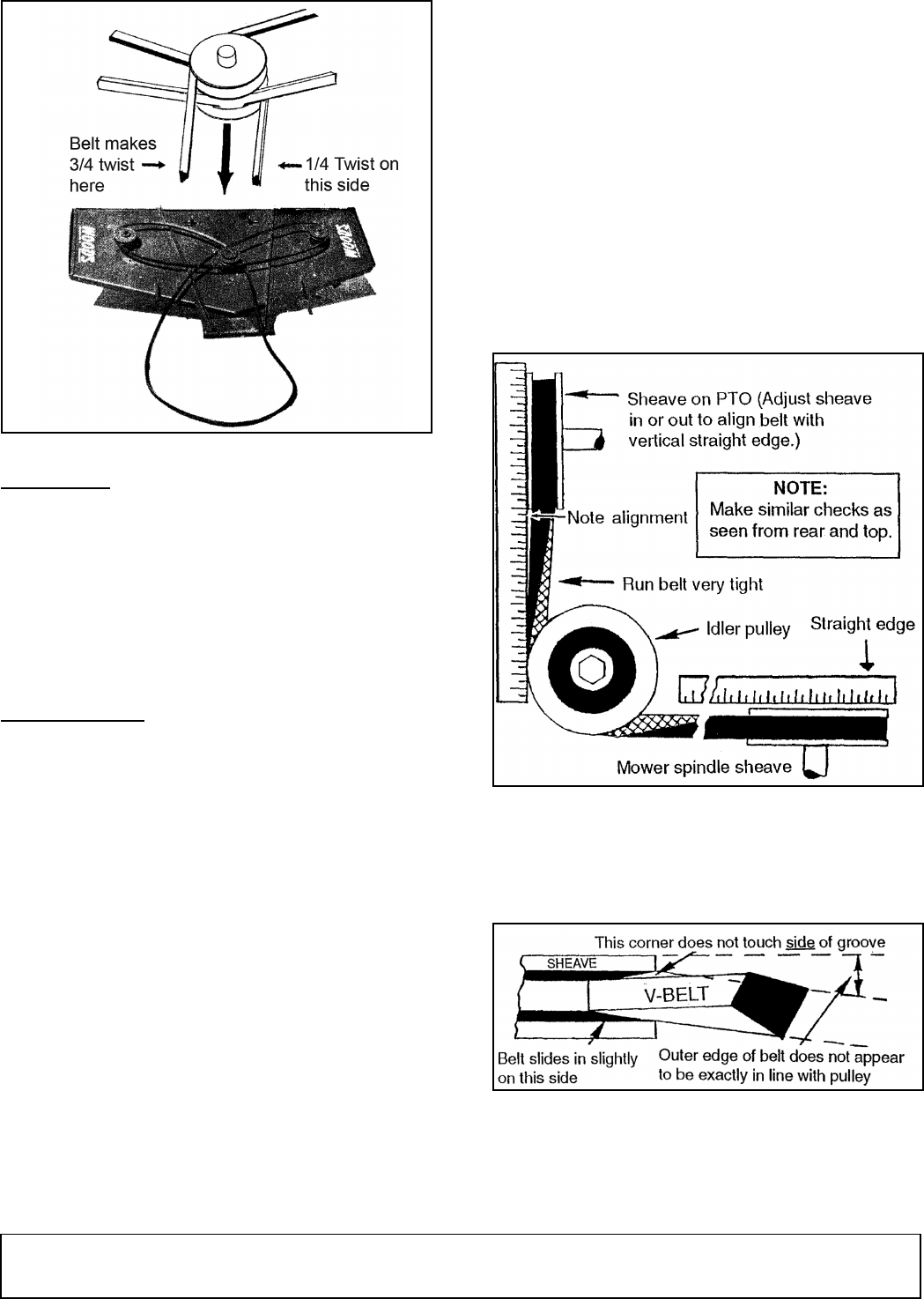
Figure 5. Belt Installation
Proper Twist
: The belt then follows with a 3/4 twist
back under the left V-idler, up over the drive sheave
and back down under the right idler pulley. This will
leave a 1/4 twist in the section of belt extending from
the right V-idler to lower groove of the center mower
sheave. If not installed correctly, more twist will result
than is allowable.
Adjust the mower to proper cutting height. The front of
the mower should be slightly lower than the rear for the
best cutting and least power requirement.
Idler Adjustment
: Make minor belt adjustment with
idlers but keep left idler about 1" above being in line
with the groove in which the belt runs on the center
sheave of the mower and right idler about 1" below.
Move mower fore and aft for major adjustments.
Belt Troubleshooting
Belt Whip
Belt whip is caused by belt misalignment unless mower
is driven by a rough-running or 2-cylinder engine. On
certain models a belt guide is provided to dampen out
the whip on the loose side. The guide should be set to
just clear the belt in normal position.
Proper Position of 59
Adjust mower forward and back to such a position that
the rear take-up idlers are near the bottom of their slots
when the belt lines up with the proper groove in the
center pulley and is tight. Never run the idlers high in
the slots as this will cause misalignment.
It is assumed that the mower is adjusted to run approx-
imately level. If the front of the mower is down, the
idlers will have to be raised. If the back of the mower is
down, the idlers will have to be down further. Belts
must be in proper alignment with sheave grooves as
shown in Figure 6 through Figure 8.
PTO Pulleys
PTO Pulleys must be moved in or out to cause the belt
to be in alignment with the idlers.
Belt Tension
Run belts very tight. Slipping will heat and ruin a belt
but tension is not harmful.
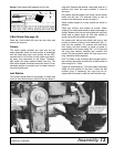
Use of Straight Edge (Side View)
Figure 6. Use of Straight Edge
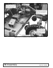
How to Align a Twisted Belt
Right: Inside edges of the belt are approximately lined
up with the sheave.
Figure 7. Correct Alignment


