


Assembly 11
29929 (Rev. 3/28/2008)
cal push arms (31 and 40) and attachment brackets
(32) and (39).
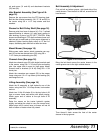
Idler Bracket Assembly (See Figure 9 &
page 16)
Remove the cap screws from the PTO bearing plate.
Bolt the idler bracket assembly (36, 37, 38 and 45) to
the tractor using 3/8 x 1-1/2" cap screws and lock
washers.
Sheave for Belt Pulley Shaft (See page 16)
Remove paint from bore of sheave (41). Put 1" splined
tapered bushing in sheave (41) and insert screws to
hold bushing in place, but DO NOT TIGHTEN. Slide
sheave and bushing on PTO shaft and leave loose until
belts are put on and lined up. After proper alignment is
obtained, tighten bushing bolts evenly to 12 lbs-ft of
torque, alternating back and forth at least six times.
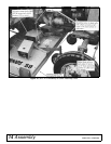
Mount Mower (See page 16)
Slide mower under tractor, attach crosswise rear sup-
port (35) to the two channel arms (33) using 5/8 x
1-1/2" clevis pins and safety pins (28).
Channel Arms (See page 16)
Attach two channel arms (33) with single bore hole end
to the mower, using 5/8 x 1-1/2 clevis pins and safety
pins. Use upper hole in arms for high grass. Attach
channel arms to brackets (31 & 40) using 5/8 x 1-3/4
clevis pins.
Attach the crosswise rear support (35) to the mower
frame using one 1/2 x 2" cap screw, pivot bushing (34)
and flange lock nut.
Lifting Assembly (See page 16)
Attach the lift assembly to right hydraulic arm of the
tractor, using two 5/8 x 1-3/4 cap screws, lock washer
and nut.
Attach two 10-link lift chains (9) to the key holes in lift
lugs on mower frame and secure with plastic caplug.
Attach upper end of chains to the eye bolts of lift
assembly.
Raise the mower on the tractor hydraulic system
slightly and adjust the chain to carry the mower level.
Adjust stops on lift control lever so mower will not hit
tires or bottom of tractor when fully raised.
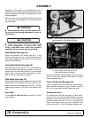
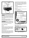
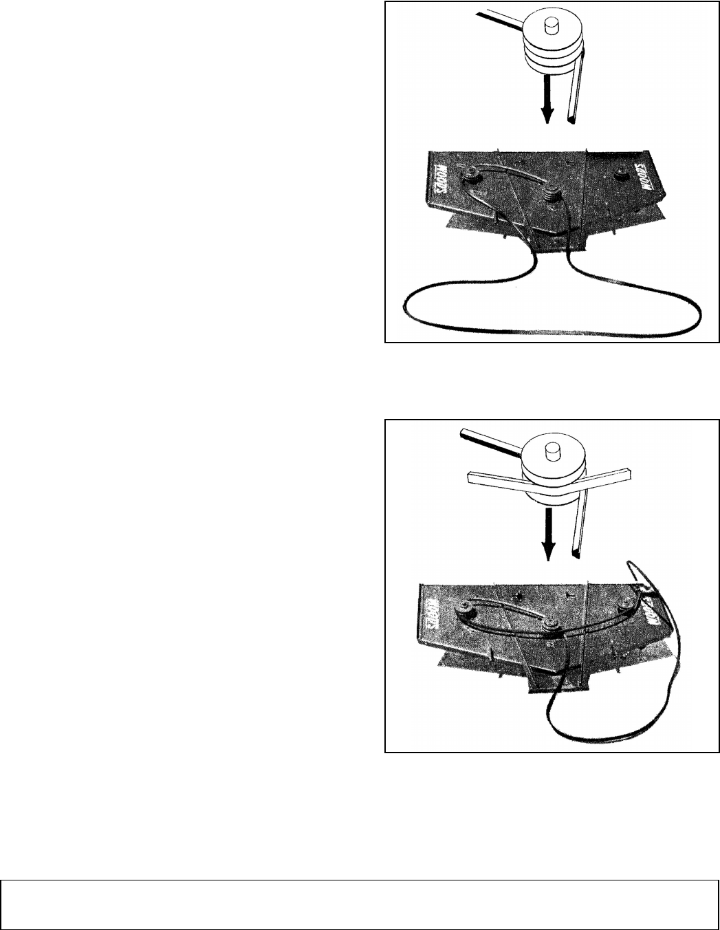
Belt Assembly & Adjustment
First put belt on bottom groove, right hand side of the
center sheave. Then thread it to the left, around the left
hand sheave.
Figure 3. Belt Installation
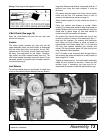
Bring the belt back across the center sheave in the
center groove over to the right outside sheave.
Figure 4. Belt Installation
Then thread it back across the front of the center
sheave in the top groove.