


Assembly 11
29900 (Rev. 7/6/2007)
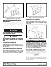
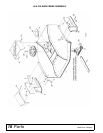
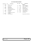
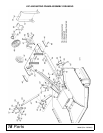
MOUNTING FRAME ASSEMBLY
Push Channel / Push Channel Mounting
Angles and Lift Bars
Loosely assemble the following (see page 18):
Attach right push channel mounting angle (53) to right
rear deck rail and rear mower deck with 1/2" x 1-1/2"
carriage bolts (83) and flange lock nuts (91). Attach left
push channel mounting angle (57) to left rear deck and
rear of mower in same manner.
Insert 1/2" x 1-3/4" bolts (85) through hole in deck rails
immediately behind belt shield. Install slotted hole in
push channel arm (54) on bolt. Install lift arm (40) on
bolt and fasten with lock washer (88) and nut (89).
Attach push channel arm (54) to channel arm mounting
angle (53) with 1/2" x 1-1/2" carriage bolts (83) and
flange lock nuts (91). Mounting angles (53 & 57) have
an upper and lower slot for a cutting height of 1" to 2".
Use lower slot when a higher cutting height is desired.
NOTE: Earlier models do not have lower slots. Should
you need to raise cutting height, drill a 9/16" diameter
hole 3/4" below the upper slot.
Should belt stretch or pulley wear cause the belt to
become too long, re-tension by moving mower forward
and using front hole in push channel arms as an
attachment point.
Leave push channel arms loosely assembled until
mower is mounted to tractor.
Belt Guide
Clamp belt guide (55) to left channel arm using clamp
plate (56) and 3/8" x 2-1/2" hex head cap screws (78),
lock washers (79) and nuts (80). After belt has been
installed, adjust guide fore and aft in the channel so the
belt runs about through the center of the guide.
Idler Bracket
Adjust tractor drawbar to center hole of its adjustment
and slide idler bracket (46) into place. Clamp idler
bracket to tractor drawbar plates with two clamp plates
(45) and four 1/2" x 2" bolts (86), lock washers (88) and
nuts (89). If for some reason, the tractor drawbar
mounting plates have been removed from the tractor,
they must be reinstalled in order to clamp the idler
bracket to them.
Idlers to Idler Bracket
Install 5/8" x 3-1/2" carriage bolt (94) in through the
right side of the vertical slots on idler bracket (46).
Place three 5/8" flat washers (9) over carriage bolt on
left side of slots. Install idlers (47) over bolt and secure
with 5/8" flat washer (95), lock washer (96) and nut
(97).
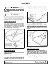
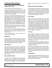
Mower Frame to Idler Bracket
Slide mower frame under tractor. Adjust front axle out
to provide clearance of mower when turning. See Fig-
ure 10. Attach push channel arms (54) to idler bracket
(46) with 5/8" x 1-1/2" clevis pins (92) and secure with
safety pins (75). Tighten all push channel arm and
mounting bracket hardware installed in
Push Channel /
Push Channel Mounting Angles and Lift Bars.
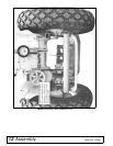
Drive Pulley
Remove paint from hub of drive sheave (48). Install
bushing (49) and slide assembly onto tractor PTO
shaft, set in from end of shaft approximately 1/2".
Loosen both idlers, place belt over drive sheave (48)
and two idlers (47). Press idlers down to tighten belt.
Then tighten nuts, keeping both idlers in about the
same relative position. Sight down over drive sheave
and align drive sheave with idlers by moving it in or out
of the PTO shaft. Then alternately tighten bushing bolts
evenly to 12 lbs-ft torque, alternating back and forth at
least six times. On IH Cub, adjust belt tension with
mower raised to 4" cutting height.
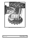
Lift Arms
Attach upper lift arm (42) to hydraulic lift arm on right
side of tractor with two 5/8 x 1-3/4" bolts (93), lock
washers (96) and nuts (97). Offset of arm (42) should
be toward the outside of tractor. Assemble center lift
arm (43) to upper lift arm (42) using 5/8 x 1-3/4" bolt
(93), 5/8 x 1 x 7/16" sleeve (44), flat washer (95) and
deformed thread nut (97).
Assemble lower lift arm (41) to center lift arm (43) with
1/2 x 1-1/2" bolt (84) and deformed thread nut (90). Do
not tighten this bolt too tight as arms (41 & 42) need to
pivot freely on this bolt.
Attach lower end of lift arm (41) to lift bars (40) using
1/2 x 2" clevis pin (87) and 3/16 x 1" cotter pin (76).
Adjust stops on lift control lever so mower does not hit
bottom of tractor or tractor tires when fully raised. For
tractors not equipped with hydraulics see page 22 for
manual lift.
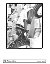
V-Belt Shield
Bolt V-belt shield attachment plate (50) to tractor plow
bracket holes with two 1/2 x 1" bolts (82) and lock
washers (88). Attach V-belt shield (51) to attachment
plate (50) with 3/8" wing nut (81).