


6
SYSTEM CONFIGURATION
ELECTRIC HEAT SYSTEMS
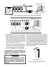
For central electric heat systems where the blower is
energized by a separate circuit through the fan relay
(meaning that the fan turns on immediately on call for
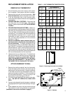
heat), clip wire W14 on the back of the thermostat (see fig.
10). If the thermostat is energizing electric heat sequenc-
ers, DO NOT clip wire W14.
ENERGY MANAGEMENT RECOVERY
(EMR)
When the EMR feature is activated, the thermostat's
mocrocomputer automatically calculates the time it will
take to change the temperature to the next program
setting. Then the thermostat will activate the heating or
cooling system to change the temperature so that the
desired temperature is reached at or near the beginning
of the next program period (the thermostat's microcom-
puter calculates 15 minutes for every 2°F temperature
change). For example, assume that the thermostat is
programmed to provide an overnight heating temperature
of 62°F, and during the next program period, programmed
to begin at 6:00 AM, the programmed temperature is
70°F. With EMR activated, the thermostat will automati-
cally activate the heating system at 5:00 AM, so that the
programmed temperature of 70°F is reached by about
6:00 AM.
The thermostat is shipped with the EMR feature inactive,
which means that the thermostat will activate the heating
or cooling system at, not before, the beginning of the
program period (real time).
To activate the EMR function, clip wire S3 on the back
of the thermostat (see fig. 10).
Figure 10. Back of Thermostat
3-pin Connector
6-pin Connector
Batteries
W14 S3
CHECK THERMOSTAT OPERATION
If at any time during testing the system does not function
correctly, disconnect electrical power at fuse box or circuit
breaker and check that all wiring is correct.
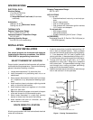
FAN OPERATION
1. Turn on power to the system. If the heat source has
a standing pilot, be sure to light it.
2. Press
FAN
ON – AUTO
until FAN ON is displayed. The blower
should begin to operate (this will work only on sys-
tems with a G terminal).
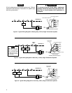
On three-wire heat only systems, or on four-wire heat/
cool systems, if the thermostat display is operating
properly, but the fan does not operate when
FAN
ON – AUTO
is pressed, the red jumper wire (provided with thermo-
stat) may not be properly installed between the RH
and RC terminals. Disconnect electrical power to
system and properly install the jumper wire per the
appropriate wiring schematic.
3. Press
FAN
ON – AUTO
until FAN AUTO is displayed. The
blower should stop operating within approximately
one minute.
HEATING SYSTEM
1. Press
SYSTEM
HEAT-OFF-COOL-AUTO
until HEAT is displayed (it may already
be displayed).
2. Press to adjust thermostat above room tem-
perature to call for heat. The heating system should
begin to operate.
OPERATION