


4
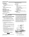
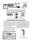
All wiring diagrams are for typical systems only. Refer to
equipment manufacturers' instructions for specific sys-
tem wiring information.
To prevent electrical shock and/or equipment
damage, disconnect electrical power at the main
fuse box or circuit breaker until installation is
complete.
NOTE
CAUTION
!
RC
Y
24vAC
120vAC
Hot
Neutral
THERMOSTAT
SYSTEM
G W
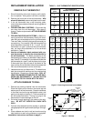
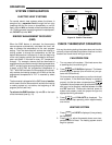
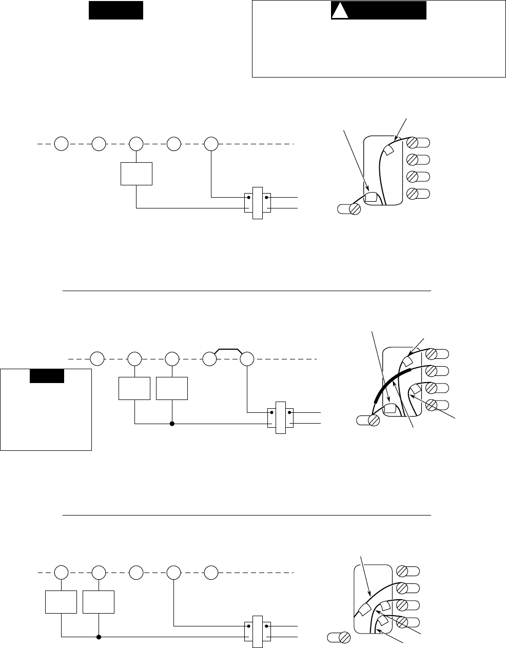
Figure 6. Typical Wiring Diagram for Cool Only, 3-Wire, Single Transformer Systems
Fan
Relay
Cooling
System
RH
TRANSFORMER
G
RC
Y
W
RH
Thermostat Terminal Connections
G
From 24vAC
transformer
From fan relay
From cooling system
RC
Y
RH
Y
24vAC
120vAC
Hot
Neutral
THERMOSTAT
SYSTEM
G W
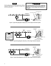
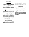
Figure 5. Typical Wiring Diagram for Heat Only, 3-Wire, Single Transformer Systems
TRANSFORMER
RC
Fan
Relay
Heating
System
JUMPER
WIRE
G
RC
Y
W
RH
W
RH
Thermostat Terminal Connections
G
From heating system
From 24vAC
transformer
From fan relay
CONNECT red jumper
wire (provided)
NOTE
RED jumper wire (pro-
vided with thermostat)
must be connected be-
tween thermostat's RH
and RC terminals for pro-
per thermostat operation
with this system.
RH
Y
24vAC
120vAC
Hot
Neutral
THERMOSTAT
SYSTEM
G W
Figure 4. Typical Wiring Diagram for Heating Only, 2-Wire, Single Transformer Systems
TRANSFORMER
Heating
System
RC
G
RC
Y
W
RH
W
RH
Thermostat Terminal Connections
From heating system
From 24vAC transformer