


5
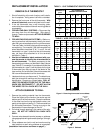
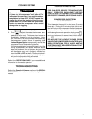
To attach thermostat to subbase, line up the plastic snap
guides at the bottom of the thermostat and the three
connector pins on the thermostat with the connectors
near the bottom left section of the subbase (when viewed
from the front). Gently pivot the thermostat up until the six
pin connectors and the plastic snaps lock into place (see
fig. 9). Be gentle when attaching thermostat. If the
thermostat does not seem to be attaching to the subbase
easily, make sure that the connector pins and plastic
snaps are properly aligned, and that excess wire is
pushed into the wall. Damage to the thermostat may
occur if force is used.
ENGAGE TWO LOWER GUIDES;
PIVOT UP
Figure 9. Attaching thermostat to subbase
CAUTION
!
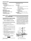
5. Move subbase out of the way. Drill mounting holes.
6. Fasten subbase loosely to wall, as shown in fig. 3,
using two mounting screws. Place a level against
bottom of subbase, adjust until level, and then tighten
screws. (Leveling is for appearance only and will not
affect thermostat operation.) If you are using existing
mounting holes, or if holes drilled are too large and do
not allow you to tighten subbase snugly, use plastic
expansion plugs to secure subbase.
7. Push excess wire into wall and plug hole with a fire-
resistant material (such as fiberglass insulation) to
prevent drafts from affecting thermostat operation.
ATTACH THERMOSTAT TO SUBBASE
IT IS RECOMMENDED THAT YOU PROGRAM THE
THERMOSTAT WITH BATTERIES INSTALLED BE-
FORE ATTACHING ON SUBBASE (see OPERATION
GUIDE for programming instructions).
POWER TO THERMOSTAT MUST BE OFF BE-
FORE ATTACHING THERMOSTAT TO WALL.
FAILURE TO TURN OFF POWER BEFORE AT-
TACHING THERMOSTAT MAY CAUSE EQUIP-
MENT DAMAGE DUE TO RAPID COMPRESSOR
CYCLING.
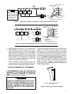
RH
Y
24vAC
120vAC
Hot
Neutral
THERMOSTAT
SYSTEM
G W
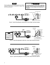
Figure 7. Typical Wiring Diagram for Heat/Cool, 4-Wire, Single Transformer Systems
TRANSFORMER
Cooling
System
Fan
Relay
Heating
System
RC
JUMPER
WIRE
G
RC
Y
W
RH
Thermostat Terminal Connections
G
From 24vAC
transformer
From fan relay
From cooling system
Y
CONNECT red jumper
wire (provided)
W
RH
From heating system
NOTE
RED jumper wire (pro-
vided with thermostat)
must be connected be-
tween thermostat's RH
and RC terminals for pro-
per thermostat operation
with this system.
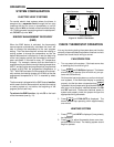
RH
Y
24vAC
120vAC
Hot
Neutral
THERMOSTAT
SYSTEM
G W
HEATING TRANSFORMER
24vAC
120vAC
Hot
Neutral
COOLING TRANSFORMER
Cooling
System
Fan
Relay
Heating
System
RC
G
RC
Y
W
RH
Thermostat Terminal Connections
From fan relay
From heating system
From 24vAC
cooling transformer
From cooling system
From 24vAC
heating transformer
Figure 8. Typical Wiring Diagram for Heat/Cool, 5-Wire, Two-Transformer System
RH
W
RC
G
Y