


6
3
Setting Up
Your Snow
Thrower
IMPORTANT: The snow thrower is shipped with oil
and WITHOUT GASOLINE. After assembly, refer to
separate engine manual for proper fuel and engine oil
recommendations.
NOTE: Remove any packing material, if present.
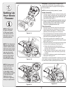
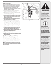
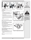
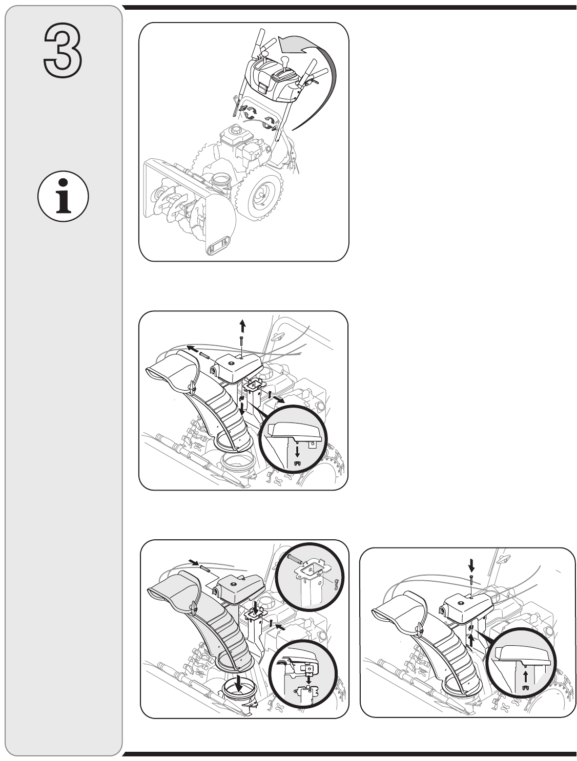
Handle Assembly
1. Observe the lower rear area of the snow thrower to be
sure both cables are aligned with roller guides. Pull up
on the upper handle, align the upper handle with the
lower handle. See Figure 3-1.
2. Secure the handle by tightening the plastic wing knob
located on both the left and right sides of the handle.
Remove and discard any rubber bands, if present.
They are for packaging purposes only.
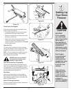
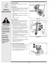
Chute Assembly
• Removewingnutandhexscrewfromchutecontrol
assembly and clevis pin and cotter pin from chute
support bracket. See Figure 3-2. Position the chute
assembly (forward-facing) over the chute base.
• Placechuteassemblyontochutebaseandsecurechute
control assembly to chute support bracket with clevis pin
and cotter pin removed earlier. See Figure 3-3.
• Finishsecuringchutecontrolassemblytochute
supportbracketwithwingnutandhexscrewremoved
earlier. See Figure 3-4.
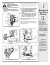
• Guidethechutecrankrodthroughthebracketlocated
on the rear of the handle panel See Figure 3-5.
a. Remove the cotter pin and insert the chute
crank rod into the connector on the chute control
assembly. See Figure 3-6.
b. Align the hole in the chute crank rod with the hole
in the connector, secure with cotter pin previously
removed.
• Checkthatallcablesareproperlyroutedthroughthe
cable guide. See Figure 3-7.
Theextensioncordisfastenedwithacabletietotherear
oftheaugerhousingforshippingpurposes.Cutthecable
tie and remove it before operating the snow thrower.
Figure 3-3
Figure 3-2
Figure 3-1
Figure 3-4
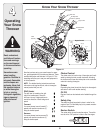
NOTE: References
to right or left side
of the snow thrower
are determined from
behind the unit in the
operating position.
NOTE: Replacement
auger shear pins are
included with this
manual (or stowed
in the plastic handle
panel). Refer to Augers
in the Maintainance
Section for more
information regarding
shear pin replacement.
NOTE: This Operator’s
Manual covers several
models, handle panels,
lights and chute cranks
are some features that
may vary by model.
Not all features refer-
enced in this manual
are applicable to all
snow thrower models.