


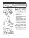

7
SECTION 5: CONTROLS
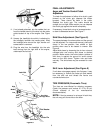
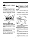
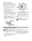
Figure 10
SHIFT LEVER
(See Figures 10 and 11)
The shift lever is located in the center of
the handle panel. The shift lever may be
moved into one of eight positions. Run
engine with throttle in the fast position.
Use the shift lever to determine ground
speed.
Forward—one of six speeds. Position
number one (1) is the slowest. Position
number six (6) is the fastest.
Reverse—two reverse (R) speeds. “R”
closest to the operator (all the way back)
is the faster of the two.
Figure 11
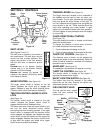
AUGER CONTROL (See Figure 10)
The auger control clutch is located on the left
handle. Squeeze the clutch grip to engage the
augers. Release to stop the snow throwing action.
(Traction control clutch must also be released.)
TRACTION CONTROL/AUGER CLUTCH
LOCK
(See Figure 10)
The traction control clutch is located on the right
handle. Squeeze the traction control clutch to
engage the wheel drive. Release to stop.
This same lever also locks the auger clutch so you
can turn the chute directional control without
interrupting the snow throwing process. If the auger
control clutch is engaged with the traction control
clutch engaged, the operator can release the auger
control clutch (on the left handle) and the augers will
remain engaged. Release the traction control clutch
to stop both the augers and wheel drive (auger
control clutch must also be released).
TRIGGER LEVERS (See Figure 10)
The trigger levers are located on the underside of
the handles and are used to help you steer your
snow thrower. To turn right, squeeze the right trigger
lever and guide the snow thrower to the right. To
turn left, squeeze the left trigger lever and guide the
snow thrower to the left. These controls should be
used while operating your snow thrower in open
areas until you become familiar with their operation.
Lift both triggers for easy transport when the engine
is not running.
CHUTE DIRECTIONAL CONTROL
(See Figure 10)
The chute directional control is located on left hand
side of the snow thrower.
To change the direction in which snow is thrown,
turn chute directional control as follows:
1. Crank clockwise to discharge to the left.
2. Crank counterclockwise to discharge to the right.
CHUTE TILT CONTROL (See Figure 10)
The distance snow is thrown can be adjusted by
adjusting the angle of the chute assembly. Move the
chute tilt control forward to decrease the distance,
toward the rear to increase.
HEADLIGHT (See Figure 10)
The headlight is on whenever the engine is running.
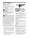
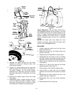
THROTTLE CONTROL (See Figure 12)
The throttle control is located on the engine. It
regulates the speed of the engine.
SAFETY IGNITION SWITCH (See Figure 12)
The ignition key must be inserted in the switch
before the unit will start. Remove the ignition key
when snow thrower is not in use.
FUEL SHUT-OFF VALVE
The fuel shut-off valve, located
under fuel tank, controls fuel
flow from tank.
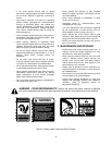
Figure 12
Auger
Control
Clutch
Chute
Tilt
Control
Shift
Lever
Chute
Directional
Left
Trigger
Lever
Right
Trigger
Lever
Headlight
Shift
Lever
Traction Control/
Auger Clutch
Lock
Control
Open
Closed
Muffler
Guard
Primer
Choke
Carburetor
Cover
Ignition
Key
Control
Lever
Oil Drain
Plug
Starter
Handle
Fuel
Tank
Fuel Fill
Cap
Oil Fill Plug
Muffler
Electric
Starter
Button
(If Equipped)