


11
SECTION 9: MAINTENANCE
WARNING: Disconnect the spark plug
wire and ground against the engine
before performing any repairs or
maintenance.
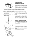
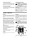
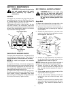
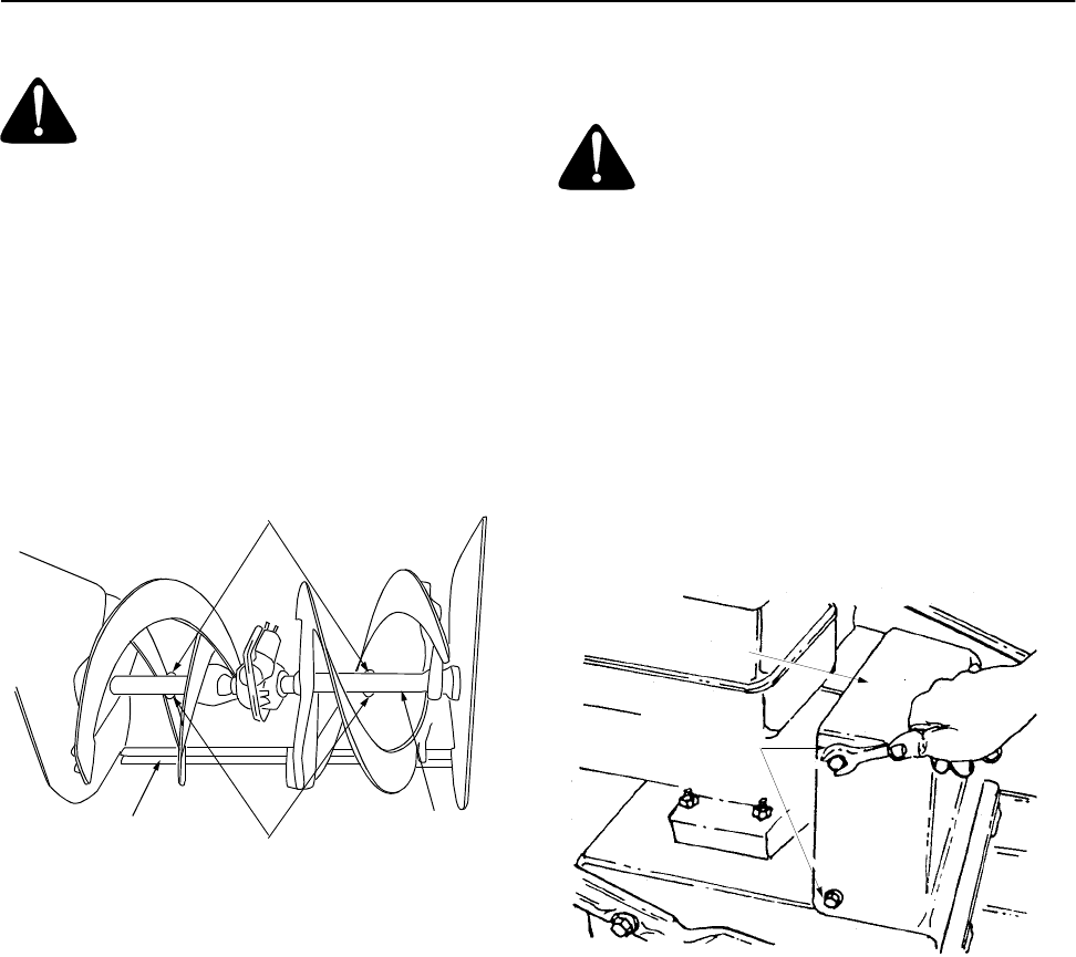
AUGERS
The augers are secured to the spiral shaft with two
shear bolts and hex lock nuts. See Figure 16. If you
hit a foreign object or ice jam, the snow thrower is
designed so that the shear bolts will shear.
If the augers will not turn, check to see if the hex
bolts have sheared. Two replacement shear bolts
and hex lock nuts have been provided with the snow
thrower. When replacing bolts, spray an oil lubricant
into shaft before inserting new bolts.
Figure 16
SHAVE PLATE AND SKID SHOES
The shave plate and skid shoes on the bottom of the
snow thrower are subject to wear. They should be
checked periodically and replaced when necessary.
NOTE: All models are equipped with reversible
skid shoes.
To remove skid shoes, remove the carriage bolts,
Belleville washers and hex nuts which attach them to
the snow thrower. Reassemble new skid shoes with
the carriage bolts, Belleville washers (cupped side
goes against skid shoes) and hex nuts.
To remove shave plate, remove the carriage bolts,
Belleville washers and hex nuts which attach it to the
snow thrower housing. Reassemble new shave
plate, making sure heads of the carriage bolts are to
the inside of the housing. Tighten securely.
BELT REMOVAL AND REPLACEMENT
WARNING: Remove the spark plug
wire from the spark plug and ground.
Drain gasoline from the fuel tank, or
place a piece of plastic film underneath
the gas cap to prevent gasoline from
leaking.
Auger Belt
To remove and replace either the auger belt or the
drive belt, proceed with the following instructions:
1. Disconnect chute directional control assembly at
the discharge chute by removing the cotter pin
and flat washer.
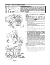
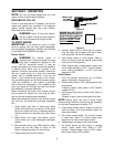
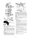
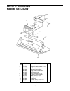
2. Remove the plastic belt cover on the front of the
engine by removing three self-tapping screws
and flat washers. See Figure 17.
Figure 17
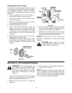
3. Remove the large shoulder bolt and washer on
the left hand side of the engine pulley with an
adjustable wrench. Refer to Figure 18.
NOTE: Reference to right hand or left hand side of
machine are observed from the operating position.
4. Remove the cotter pin and washer from the
ferrule in order to disconnect the auger idler rod
from the brake bracket assembly as shown in
Figure 19.
5. Slip the auger control belt (the front belt) off the
engine pulley. Refer to Figure 19.
6. Pull the brake bracket assembly towards the
cable guide roller and unhook the auger cable
“Z” fitting.
7. Remove the top screws and lock washers which
attach the auger housing assembly to the frame
assembly. A 9/16” wrench is required. Refer to
Figure 20.
Auger Shaft
Auger Shear Bolts
Hex Lock Nuts
Shave Plate
Belt
Cover
Self-Tapping
Screw
Flat Washer