


10
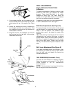
SHIFT ROD ADJUSTMENT
To adjust the shift rod, remove the cotter pin which
secures the shift rod to the shift lever. For proper
adjustment, refer to FINAL ADJUSTMENTS on page
6.
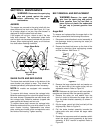
SKID SHOE ADJUSTMENT
The space between the shave plate and the ground
can be adjusted. Refer to Skid Shoe Adjustment
(See Figure 8) on page 6.
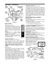
CARBURETOR ADJUSTMENT
WARNING: If any adjustments are
made to the engine while the engine is
running (e.g. carburetor), keep clear of
all moving parts. Be careful of heated
surfaces and mufflers.
Minor carburetor adjustment may be required to
compensate for differences in fuel, temperature,
altitude and load.
Refer to the separate engine manual packed with
your unit for carburetor adjustment information.
NOTE: Failure to comply with suggested
maintenance and lubrication specifications on page
10 and page 11 will void warranty.
SECTION 8: LUBRICATION
WHEELS
Oil or spray lubricant into bearings at wheels at least
once a season. Remove wheels, clean and coat
axles with a multi-purpose automotive grease. See
Figure 15.
CHAINS AND SHIFTING MECHANISM
Remove lower cover. Oil all chains, sprockets,
bearings, the hexagonal shaft, round shaft, and
shifting mechanism at least once a season. Use
engine oil or a spray lubricant. Avoid getting oil on
rubber friction wheel and aluminum drive plate.
CHUTE DIRECTIONAL CONTROL WORM
The worm gear on the chute directional control
should be greased with multi-purpose automotive
grease.
IMPELLER PULLEY
The impeller pulley should be lubricated once a
season. Refer to exploded view of parts, found in the
back of the book, for correct location.
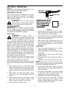
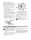
AUGER SHAFT
Remove auger bolts on auger shaft, see Figure 16.
Oil or spray lubricant inside shaft.
ENGINE
Refer to engine manual for engine lubrication
instructions.
HEX SHAFT
Lubricate the hex shaft with a good all-weather multi-
purpose light grease at least once a season or after
every 25 hours of operation (available from an
authorized service dealer or an automotive store.)
See Figure 15.
If for any reason your transmission was
disassembled and the auger cable disconnected,
make sure when reassembling to pass the cable
above the hex shaft before reconnecting to the
auger actuator bracket.
WARNING: When following instruc-
tions in separate engine manual for
draining oil, be sure to protect frame to
avoid oil dripping onto transmission
parts.
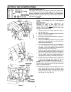
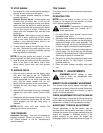
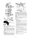
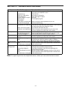
Figure 15 Viewed from the underside of snow
thrower
Auger
Actuator
Shift Arm
Assembly
Drive
Actuator
Hex
Shaft
Friction
Wheel
Hex Nut
and
Cupped
Washers
Bracket
Bracket
Trigger
Cables