


48
6.3 Connecting the ECG Electrodes
Prepare the patient’s skin, attach the leads to the electrodes, place the electrodes in the three (or five)
correct locations, and plug the ECG cable into the monitor. The heart rate alarm usually operates in
conjunction with the ECG measurement.
Connecting - Connect the ECG leads to the
patient:
• Thoroughly clean the patient’s skin at each
place where an electrode will be attached.
Shave if necessary. Attach lead wires to the
electrodes before applying them to the
patient.
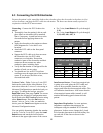
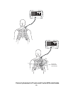
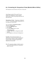
• Apply the electrodes to the patient as shown
in the diagrams for 3 wire and 5 wire
locations.
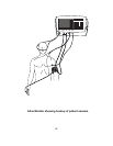
• Attach the ECG cable to the front panel
connector.
• Support the ECG cable so it does not stress
the electrode wires, the ECG cable
connectors, or electrodes. Ensure that
conductive parts of the electrodes and their
connectors do not contact any other
conductive parts, including earth.
• Verify that the monitor is configured for the
number of leads you are using.
•
You should now see an ECG waveform
scrolling across the upper part of the monitor
screen. If you do not, check the wires,
electrodes and cable.
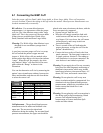
3 wire or 5 wire - Either 3 wire or 5 wire ECG
leads can be used with the Atlas Monitor. You
must select either the 3 wire or 5 wire setting in
Advanced Configuration
to match the leads you
are using. To change the lead set, press the
Date/Time button, then press Trend. The screen
will display the Advanced Configuration menu.
Scroll down to the ECG lead set selection using
either
Select button. Press the Set button to
choose 3 wire or 5 wire. After you make the
choice, press the
Trend button again to exit the
Advanced Configuration menu.
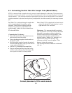
You can quickly determine whether the monitor
is set for 3 wire or 5 wire ECG: press the
Lead
Select
button and watch the lead selection
indicator in the upper right corner of the screen.
• For 3 wire, Lead Select will cycle through I,
II, III
.
• For 5 wire,
Lead Select will cycle through I,
II, III, aVR, aVL, aVF, V
.
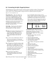
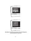
3 Wire Lead Colors & Symbols
Lead
AHA
IEC
Right arm White
RA
Red
R
Left arm Black
LA
Yellow
L
Left leg Red
LL
Green
F
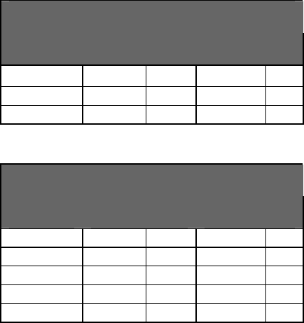
5 Wire Lead Colors & Symbols
Lead
AHA
IEC
Right arm White
RA
Red
R
Left arm Black
LA
Yellow
L
Left leg Red
LL
Green
F
Right leg Green
RL
Black
N
Chest Brown
V
White
C
Interference factors - If an electrosurgical unit
is going to be used, place the ECG cable and
wires as far as possible from the site of the
surgery and from the electrosurgical cables. This
will minimize interference. Also ensure that the
electrosurgical return cable (neutral) is well
attached and making good contact with the
patient.
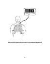
Impedance Respiration – In some patients,
impedance respiration detection may be
inadequate using the standard ECG electrode
placement. In these cases, change the LA and
RA electrode placement to the mid-axillary line
on each side of the chest as shown in the
illustration.