


4
ASSEMBLY
WARNING: If received assembled,
review allassembly steps toensure your unit
is properly assembled and all fasteners are
secure.
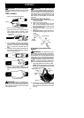
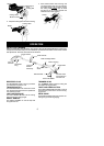
TUBE ASSEMBLY
Wires
Upper Locking Sleeve Assembly
Lower Locking Sleeve Assembly
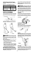
1. Align upper tube groove with triangle on
lower locking sleeve assembly . Push
tubes together until they snap into place.
Alignment Triangle
Upper Tube
Groove
2. T ry to pull tubes back apart. If the tubes do
not come apart, they are properly snapped
into place. If the tubes come apart, repeat
step 1 and push until the tubes snap into
place.
3. Slideupperlockingsleeveassemblyover
lower locking sleeve assembly andtight-
en by turning clockwise.
4. Ensure locking sleeve assembly and
alignmentdecalsappearasillustratedbe-
low.
Alignment decals
WARNING: Failure to completely en-
close excess wires inupper tubeduring a ssem-
bly of the unit may result in damag eto thewires
and/or the unit or serious injury to the operator
including electrocution.
WARNING: The upper and lower
tubes mustbe snappedtogether, remain per-
manentlyassembledtogetherandthelocking
sleeve assembly must be fully tightened be-
fore and during use to avoid serious injury to
the operator and/or damage to the unit. DO
NOT attempt to disassemble unit after initial
assembly.
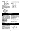
ADJUSTING ASSIST HANDLE
1. Loosen and remove wing nut and bolt
from assist handle.
2. Place unit on a f lat surface.
3. Firmly push the assist handle over the
tube. Tomake installationeasier,tilt han-
dle toward trigger housing while pushing
down (see illustration).
4. Reinstall bolt in handle. Thread wing nut
onto bolt.
5. Adjust the handle up or down the tube to a
comfortable position; tighten wing nut se-
curely.
Tube
Assist handle
Trigger
housing
ATTACHING EDGE GUIDE AND
SHIELD
WARNING: The shield must be prop-
erly installed. The shieldprovides partialprotec-
tion to the operator and others from the risk of
thrown objects. Y our unitis equipped with a line
limiter blade,whichcuts excess line t o theprop-
er lengthwhile running. Thelinelimiter blade(on
underside of shield) is sharp and can cut you.
NOTE: If shield is not properly installed, dam-
age to unit (including motor failure) will result.
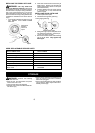
1. Insert edge guide into two holes in shield.
NOTE: Edge guidemustbe positionedon
shield prior to installation on motor housing
(see following illustration).
Edge Guide
Shield
Rear Locking
Tabs
Front
Locking
Tab
2. Placeshieldovercuttingheadat anangle
to the motor housing. Insert front locking
tabonshield intoopeninginfront ofm otor
housing.