


5
ASSEMBLY
WARNING: Stop the unit and di s-
connect from the power source befor e
opening theinlet coveror att empt ing toin-
sert or remove the inlet restrictor , blower
tube, or vacuum tubes. The motor must
be stopped and the impel l er b l ades no
long er t urning to avoid serious inju ry from
the r otat i ng bl ades.
WARNING: I freceivedassembled,
ensur e your unit is proper ly a ss em bled
and all f astener s ar e secure.
S A standard screwdriver is required for as-
sembly.
BLOWER ASSEMBLY
NOTE: Assembly instruct ions for using
your uni t as a vacuum follow t hi s s ect ion.
Attaching the blower tube
Ifyouhave alreadyassembled yourunit
foruse asa vacuum,refertothe section
HOW TO CONVERTUNIT FROM VACUUM
USE TO BLOWER USE.
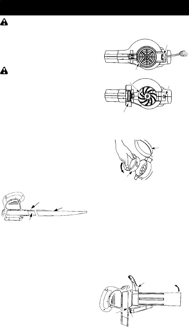
To attach blower tube:
1. Align thegrooves onthe blowertube
with thegrooves onthebloweroutlet.
2. Pushtheblowertubeontotheblower
outletuntilitsnaps intoplace (tubeis
secured by red tube release button).
3. To remove the bl ower tube, pr ess the
tube release button while pulling on
tube.
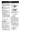
Blower Tube
Blower outlet
Tube Release Bu tton
VACUUM ASSEMBLY
NOTE: Assembly instructions for using
yourunitasablowerareexplainedinthe
previous section.
If you have alr eady assem bled your unit
for use as a blower, rem ove t he blower
tube.
Remove the inlet restrictor
An inlet restrictor is used when using your
unitas ablower. This restr i ctoris not used
duringvacuum use andmust beremoved
during assembly f or v acuum use.
NOTE: Be sure to keep the inlet re-
strictor for using your unit as a blower.
1. Ensure unit i s stopped and extension
cord is unplugged.
2. Open the inlet cover by inserting the
tipofascrewdriverintothelatcharea
on the blower u nit. Gently tilt handle
of screwdrivertoward the front of the
unit to release the latch while pulling
up on the vacu um inlet cover with
your other hand.
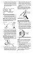
Vacuum Inlet Cover (closed)
Latch Area
Bottom view
of unit
Vacuum Inlet Cover (opened)
Latch Area
Impeller
3. T urn the inlet restrictor counterclock-
wise and remove it from the unit. Do
not close the i nl et door. You will next
att ach the vacuum tubes.
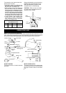
Inlet
Restrictor
Vacuum
Inlet Cover
Attaching the vacuum tubes
There are 2 v acu um tubes, an upper
tube and a lower tube. The upper tube
has a vacuumas sist handle attachedto
oneendandiscutstraightonbothends.
The upper tube attaches to the blower
unit. The lower tube has an angled end
that you point toward the ground during
vacuumuse. Thelowertubeattachesto
the upper tube.
1. Ensure unit is stopped and exten-
sion cord is unplugged.
2. Whi l e holding inlet cover open, place
th ehooksof thevacuumassisthandle
on t h e retaini ng posts of the unit .
3. Raise the tube until i t i s secured to the
blowerunit by the red i nlet coverlatch.
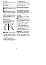
Retaining Post
Vacuum Assist Handle
Upper
V
acuum Tube
Hook