


5
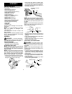
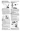
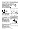
ATTACHING THE CONTROL
HANDLE TO THE HANDLEBAR
NOTE:
Make sure the wire going to the con-
trol handle is routed below the tube and re-
mains on the right side of the handlebar and
the tube.
Screw Hole
Screw
S
Slide handle onto the right side of the han-
dlebar and align the screw hole.
S
Insert screw and tighten securely.
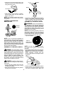
NOTE:
Make sure the control handle is on
the right side of the unit as shown in the il-
lustration below,and the On/Stop switch is lo-
cated on the top of the control handle.
S
Adjust the handlebar to the proper position
and tighten the two screws you left loose
during handlebar assembly. Make s ure
these screws are securely tightened.
S
After attaching the control handle and tight-
ening the handlebar, route the wire from the
control handle through the slit in the bottom
of the foam gri p.
Slit
Wire
Foam Grip
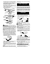
ASSEMBLY OF SHOULDER STRAP
WARNING:
Proper shoul der strap
and handlebar adjustments before starting the
engine ar e required.
S
Tr y on shoulder strap and adjust for fit and
balance before starting the engine or begin-
ning a cutting oper ation.
S
Insert your right arm and head through the
shoulder strap and allow it to rest o n your
left shoulder. Make sure the danger sign is
on your back and the hook is to the right
side of your waist.
NOTE:
A one-half twist is built in the shoul-
der strap to allow the strap to rest flat on the
shoulder.
S
Adjust the strap, allowing the hook to be
about 6 inches below the waist.
S
Fasten the strap hook to the c lamp located
between the foam grip and the mounting
block and lift the tool to the operating posi-
tion.
CONFIGURING YOUR UNIT
Yo u can configure your unit using a cutting
head for grass and light weeds, or a brush
blade for cutting saplings andsimilar size ma-
terial. Go to the section for the desired
configuration and follow the instructions for
assembling your unit.
ASSEMBLY INFORMATION --
TRIMMER HEAD
TRIMMER
HEAD
NOTE:
If your unit has been assembled for
brushblade use, refer to the s ection AS-
SEMBLY INFORMATION FOR USING
YOURUNITWITH ABRUSHBLADE andre-
verse the steps to remove the metal shield
and blade bef ore you mount the plastic shield
and trimmer head.
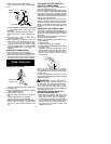
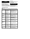
ATTACHING THE PLASTIC SHIELD
AND TRIMMER HEAD
WARNING:
The shield m ust be pr op-
erly installed. The s hieldprovides partial pr otec-
tion from therisk of thr ow n objectsto the opera-
tor and other s and i s equi pped w ith a line lim iter
whichcuts e xcess l ineto the proper l ength. The
line limiter (on underside of shield) is shar p and
can c ut you.
S
Remove wing nut from shield.
S
Insert bracket into slot on shield.
S
Pivot shield until bolt passes through hole in
bracket.
S
Tighten the wing nut securely.
S
If your uni t has a plastic cover over the
threads on the threaded shaft, r emove the
covering to expose the thr eads.
S
Before installing the trimmer head, make
sure the dust cup and retaining washer are
positioned on the gearbox as shown below.
Wing Nut
Retaining W asher
Dust Cup
Bracket
Slot
Shield
Gearbox
NOTE:
Make sure all parts are properly
installed as illustrated in the illustration before
installing the trimmer head.
S
Align hole in thedust cup with thehole inthe
side of t hegearbox byrotating the dustcup.