


Page 6
WATERPIK TECHNOLOGIES INC.
7. Disconnect the heater and its individual shutoff
valve from the gas supply system during pressure
testing of the system at pressures higher than 1/2
pounds per square inch (psi) (3.45 kilopascals
[kPa]). If the test pressure is equal to or less than
1/2 psi (3.45 kPa), close the manual shutoff valve
on the heater during the piping pressure test.
Caution
Permanent damage to the gas valve will occur
if the following procedures are not followed.
8. If the gas supply pressure is less than required,
check for undersized pipe between the meter and
the heater, a restrictive fitting, or an undersized
gas meter. Gas supply pressures to the heater are
listed in Table 4.
NOTE: The maximum inlet gas pressure must
not exceed the specified value. The minimum value
listed is for the purpose of input adjustment. Refer to
Table 4.
9. Before operating the heater, test the complete gas
supply system and all connections for leaks using
a soap solution. Do not use an open flame.
Caution
Some leak test solutions (including soap and
water) may cause corrosion or stress cracking.
Rinse the piping with water after testing.
2E-2. Special Precautions for Propane
Gas
Liquefied petroleum (LP) gas is heavier than air.
Therefore, do not install pool heaters using LP gas in
pits or locations where gas might collect. Locate
heaters a safe distance from LP gas storage and filling
equipment. Consult local codes and fire protection
authorities about specific installation restrictions.
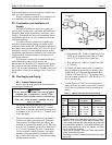
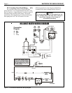
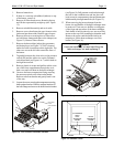
5. Install a sediment trap (drip leg) ahead of the gas
controls (see Figure 5). Fit the trap with a
threaded cap which can be removed for cleaning.
6. Install a manual gas shutoff valve for service and
safety. Do not use a restrictive gas cock. DO
NOT USE FLEXIBLE GAS PIPING.
2F. Electrical Wiring
Caution
Label all wires prior to disconnection when
servicing controls. Wiring errors can cause
improper and dangerous operation.
Verify proper operation after servicing.
Attention
Au moment de l'entretien des commandes,
étiquetez tous les fils avant de les débrancher.
Des erreurs de câblage peuvent entraîner un
fonctionnement inadéquat et dangereux.
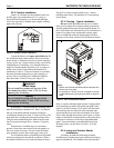
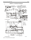
2F-1. General Information (LD Only)
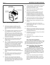
Wiring connections must be made exactly as
shown in the wiring diagram found on the inside of the
heater (see Figures 6 and 7 for typical examples) . The
heater must include a definite means of grounding.
There is a bonding lug on the right side of the heater,
where a bond wire must be attached.
The heater comes factory-wired intended for
use with 240 Volt, 60 Hz AC field electrical supply.
To use 120 Volt, 60 Hz AC requires rewiring of the
heater. This should be done by a certified electrician
only, as with all wiring. To wire the heater for 120
Volt, 60 Hz AC, follow the alternate 120V wiring
method depicted in Figure 6. Additionally, the ignition
control module must be rewired. The wire from the
terminal marked IGN/240 must be removed from that
terminal and placed on the terminal marked IGN/120.
Electrical wiring must be in accordance with the
latest edition of the National Electric Code (NEC),
ANSI/National Fire Protection Association (NFPA)
70, unless local code requirements indicate otherwise.
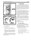
To wire the Laars Lite 2 model LD heater to a
120V or 240V /60 Hertz (Hz) electrical source:
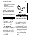
1. Remove the screw located to the lower right side
of the transformer and open the hinged cover of
the wiring enclosure.
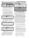
2. Connect the wires from the power source to the
leads on the right side of the heater in the space
behind the ignition control (see Figure 8). Be sure
to follow the wiring diagram on page 7 to config-
ure the transformer for the correct input voltage.
3. Attach the ground wire to the green ground screw
located on the back panel of the wiring enclosure.
4. Close the cover of the wiring enclosure and
replace the screw to hold it in place.
5. Connect a bonding wire (8 ga copper) to the
bonding lug on the right side of the heater.
NOTE: No external junction box is required.
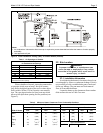
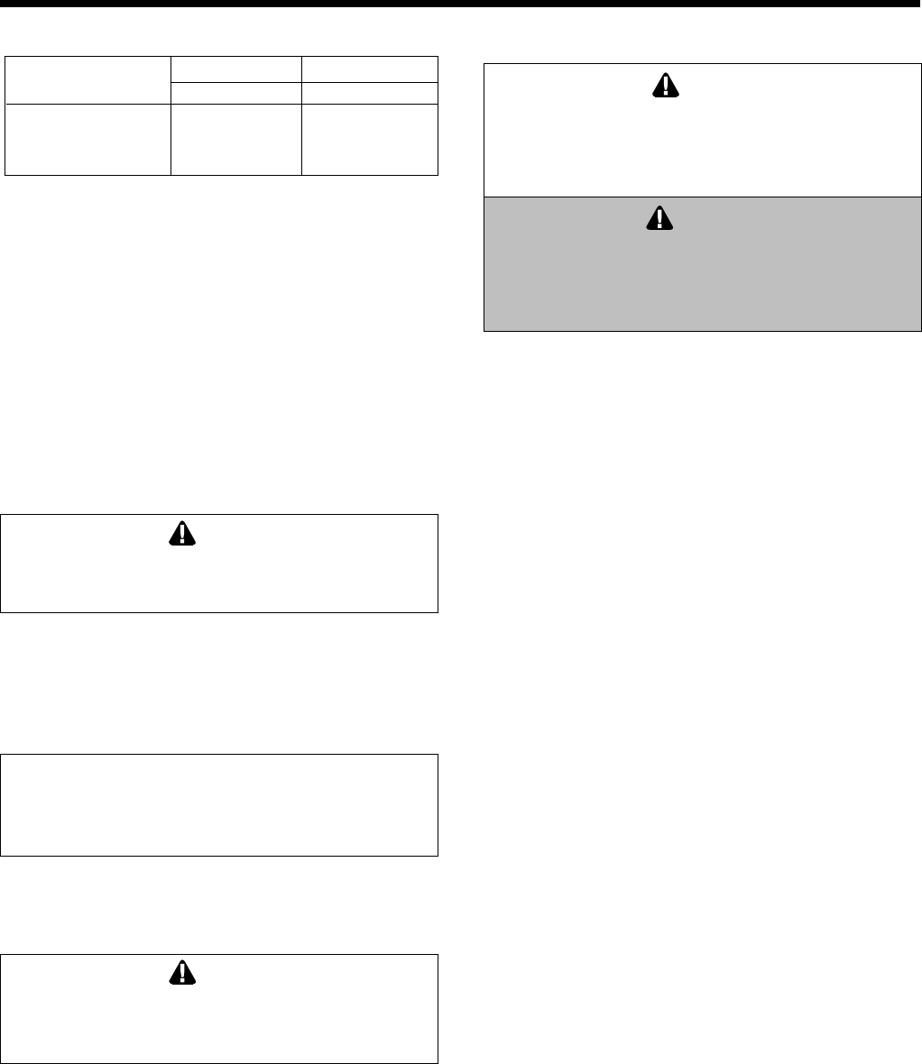
Table 4. Gas Supply Pressure Requirements
Supply Pressure Natural Gas Propane Gas
Water Column in. (mm) in. (mm)
Minimum 5.5 (140) 10.0 (254)
Maximum 10.0 (254) 14.0 (356)