Model LG & LD Pool and Spa Heater
Page 5
without modification and in accordance with all local,
state, provincial and national codes.
Proper ventilation of exhaust and combustion air
are essential for the safe operation of the heater.
2D. Combustion and Ventilation Air
Supply
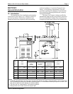
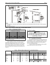
All indoor installations must have openings to
outside air for combustion, ventilation, and dilution of
flue gases from inside the building (see Figure 2 and
Table 1). Waterpik Laars does not recommend indoor
installations that do not provide combustion air from
outside the building.
All outdoor shelter installations (Canada only)
must have uninterrupted openings to outside air for
combustion and ventilation. The installation must be in
accordance with the latest edition of CAN/CGA B149.
Waterpik Laars does not recommend outdoor shelter
installations that depend on internal air for combustion.
Combustion air should be ducted to the heater from
outside the structure.
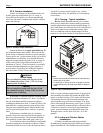
If the heater is installed in a residential garage, or
where flammable vapors will be present, the
burners must be 18 inches (457 mm) above the garage
floor. Refer to the latest edition of the National Fuel
Gas Code for more information. In Canada, refer to the
latest edition of the Gas Installation Code, CAN/CGA
B149.
2E. Gas Supply and Piping
2E-1. General Instructions
Review the following general instructions before
continuing the installation.
WARNING
Do not convert this heater from natural gas to
propane gas, or propane to natural. Field
conversion could create carbon monoxide gas
which can cause property damage, serious
injury, or death.
1. Gas piping installation must be in accordance
with the latest edition of ANSI Z223.1 and all
local codes. In Canada, the installation must be in
accordance with CAN- B149.1 or .2 and all local
codes that apply.
2. Check the rating plate to make sure the heater is
fitted for the type of gas being used. Waterpik
Laars heaters, as shipped from the factory, are
certified to operate at an altitude of 0 to 3000 feet
(0 to 915 m) for natural gas and 0 to 5000 feet (0
to 1525 m) for propane gas in the United States.
Or if so ordered, at higher altitudes. For higher
altitudes, the heater manifold is marked with a
tag or sticker indicating one of the following high
altitude operation codes:
a. High altitude (H) - 3,000 to 6,000 feet (915 to
1,830 m) for natural gas and 5000 to 10,000
feet (1525 to 3050 m ) for propane gas.
b. High altitude (J) - 6,000 to 10,000 feet (1830
to 3,050 m)
3. In Canada, the heater rating plate is marked for
specific altitude requirements: lo altitude is 0 to
2,000 feet (0 to 610 m) and high altitude (H) is
2,000 to 4,500 feet (610 to 1,370 m) above sea
level for natural gas and 0 to 4500 feet (0 to 1370
m) for propane gas.
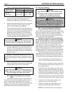
4. Use the figures in Table 3 to size the gas inlet
piping from the gas meter to the heater. Check all
local codes for compliance before installing the
heater.
Table 3. Natural Gas Pipe Size Requirements
Distance from Gas Meter
0-50 feet 50-100 feet 100-200 feet
Heater (0-15 m) (15-30 m) (30-60 m)
Size in. (mm) in. (mm) in. (mm)
125 3/4 (19) 1 (25.4) 1 (25.4)
175 1 (25.4) 1 (25.4) 1-1/4 (31.75)
250 1 (25.4) 1-1/4 (31.75) 1-1/4 (31.75)
325 1-1/4(31.75) 1-1/4 (31.75) 1-1/2 (38)
400 1-1/4(31.75) 1-1/2 (38) 1-1/2 (38)
Notes:
1. These numbers are for natural gas (0.65 Sp. Gr.) and are
based on 1/2 inch (13 mm) water column pressure drop.
Check supply pressure with a manometer, and local code
requirements for variations. For liquefied petroleum gas,
reduce pipe diameter one size, but maintain a 3/4 inch
(13 mm) minimum diameter.
2. Check supply pressure and local code requirements
before proceeding with work.
3. Pipe fittings must be considered when determining gas
pipe sizing.
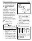
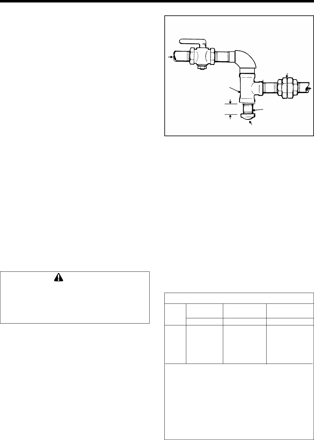
Manual Shutoff
Valve
Gas Supply
Inlet
To
Equipment
Inlet
Union
Cap
T-Fitting
3" Min.
(76 mm)
Nipple
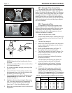
Figure 5. The proper design for a sediment trap / drip
leg.


