


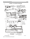
Model LG & LD Pool and Spa Heater
Page 11
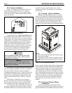
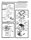
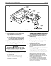
1. Remove heater door.
2. If there is a vent cap or drafthood (indoor) on top
of the heater, remove it.
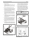
3. Remove all 8 hex-head screws fastening the top
and lift the top assembly straight up (see Figure
12).
4. Remove rainshield assembly and set it aside.
5. Remove screws that fasten the gap closures to the
jacket and put them aside. Remove gap closures.
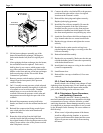
6. Remove the screws securing the two flue collec-
tor hold down clamps and remove the clamps (see
Figure 13). Remove flue collector.
7. Remove the three rubber jacket/plug grommets
and drain plugs (see Figure 12). One is located
under the water connections on the right side. The
other two are on the left side toward the front of
the heater.
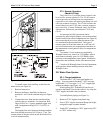
8. Tag and disconnect the white wire on the pressure
switch (PS) and the white wire on the Fireman's
switch terminal (see Figure 6 or 7) which leads to
the high limit switch.
9. Remove plastic tie wraps and pull the white wires
out of the front compartment through the vesti-
bule cover and coil them on the heat exchanger.
10. Unscrew the brass compression fitting securing
the pressure switch to the inlet/outlet header.
Remove tube from header and gently bend it out
of the way.
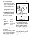
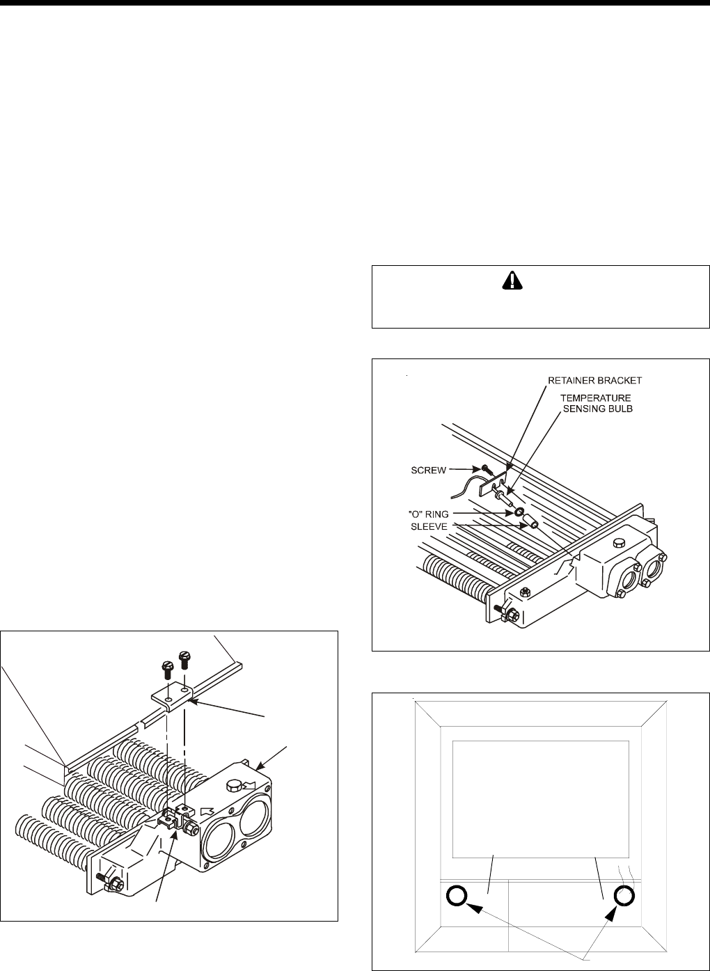
11. Loosen the screw securing the temperature sensing
bulb retainer bracket. Slide the retainer bracket off
the bulb flange and remove the bulb from the header
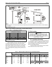
Figure 13. Flue collector hold-down brackets.
HOLD DOWN
CLAMP
IN/OUT HEADER
BRACKET
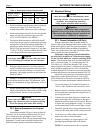
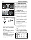
Figure 15. Vestibule covers.
FRONT PLASTIC BUSHING
LEFT
VESTIBULE
COVER
RIGHT
VESTIBULE
COVER
(U.S. MODELS
ONLY)
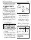
Figure 14. Temperature sensing bulb.
(see Figure 14). Pull pressure switch tube through
the hole in the vestibule cover and into the vesti-
bule (controls compartment), then pull thermostat
bulb assembly through same hole (see Figure 15).
12. When removing the heat exchanger from the
heater, the end baffles of the heat exchanger must
be removed. There are two baffles covering part
of the front and rear tubes of the heat exchanger.
Each baffle is held in place by two screws which
mount to the top of the combustion chamber wall.
Remove the screws and the baffles before at-
tempting to lift the heat exchanger out of the
heater (see Figure 16).
Caution
It may be necessary to have help lifting the
heat exchanger out and replacing it.