


Assembly Instructions
19
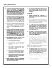
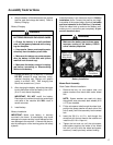
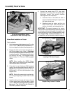
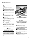
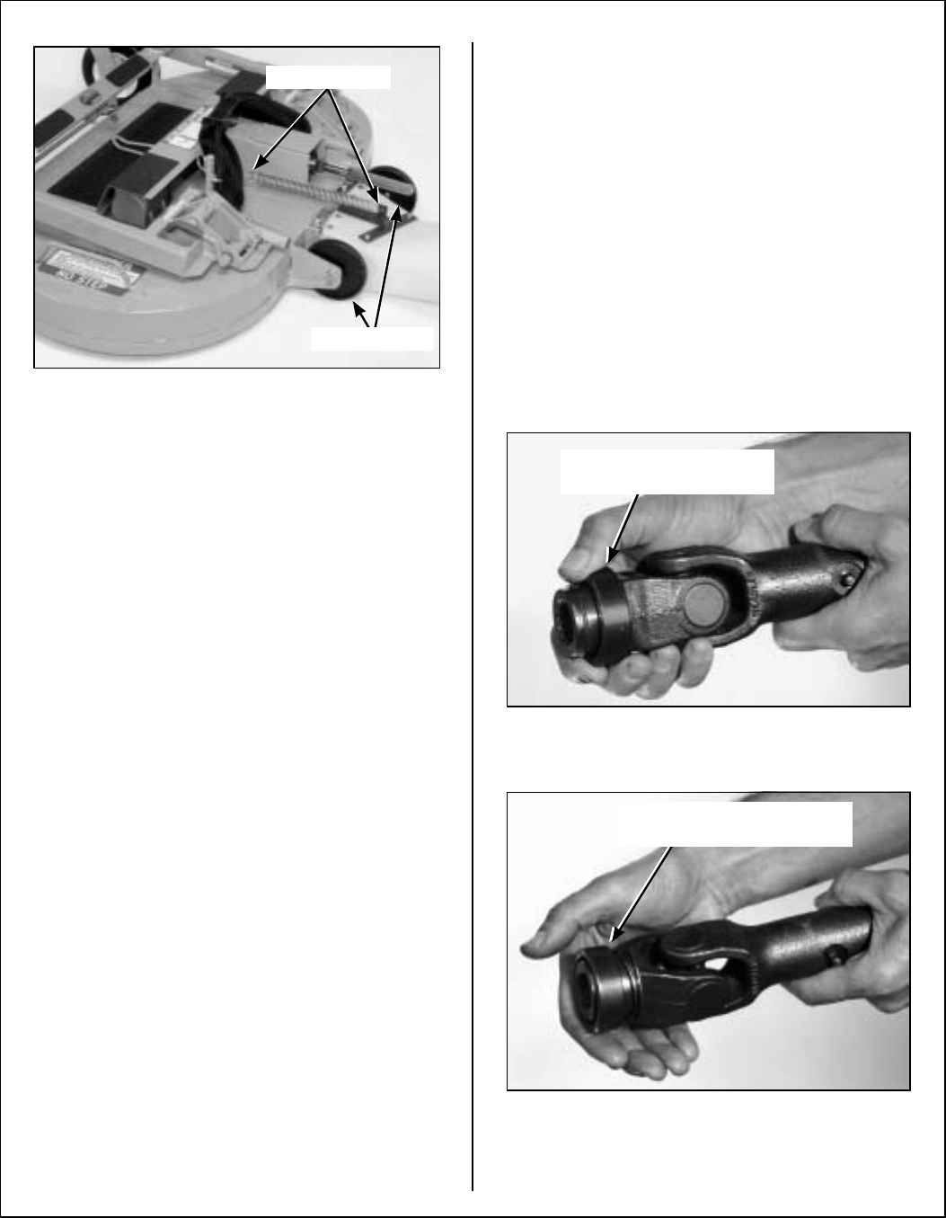
Tilt-Up Spring and Roller Wheel
Installation on Rear Discharge Deck
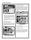
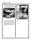
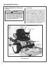
Mower Deck lnstallation on Tractor
Deck Installation
1. Lightly grease each deck support arm (2) on the
tractor. Refer to Mower Deck Installation pho-
to on next page for location of deck support arm.
2. Engage the deck carrier frame tube sockets on
the tractor support arms (refer to Discharge
Chute and PTO Shaft Guard Installation photo
for socket location). Slide the deck onto the sup-
port arms: all the way if SD equipped model,
approximately 3 in. (76 mm) if GHS equipped
model.
NOTE: When installing the DSD52 Mower
deck, make sure to retract the dolly wheel after
mounting the deck on the tractor.
3. If the deck is rear discharge (GHS equipped
model), the rear discharge chute will need to be
aligned and connected to the blower inlet dur-
ing the last 2 in. (51 mm) of slide action on the
support arms.
NOTE: Raising the mower body may be help-
ful in fitting and guiding the deck chute into the
blower.
4. Install the hitch pin through the hole on the end
of each support arm to lock the deck in place
(refer to Deck Counterweight Spring Installa-
tion photo). Two (2) hitch pins are included in
the owner’s packet of materials.
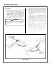
5. Connect the mower deck PTO drive shaft
assembly to the tractor with the splined quick
disconnect coupler. This coupler simplifies
shaft alignment and installation.
a. Use the arrows on the shaft and tube to
align and slide the PTO quick coupler onto
the deck splined shaft.
b. Reaching under the tractor, pull the ring
back on the coupler, slide onto the spline
shaft on the tractor, and release the ring.
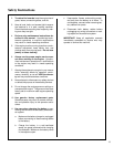
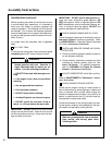
IMPORTANT: To prevent damage to the mower,
make sure the PTO shaft assembly is securely locked
on the tractor, with the locking balls fully seated in the
groove and the ring in the full forward position (refer
to the Coupler Ring “Locked” Position photo). Af-
ter installation, pull on the shaft to check for security.
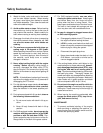
Installing PTO Quick Coupler
Coupler Ring “Locked” Position
Attach Spring
Roller Wheels
Pull Back Spring-Loaded
Coupler Ring
Spring-Loaded Coupler Ring
In Fully Forward Position