


ASSEMBLAGE
OM 0352SB-A 14
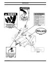
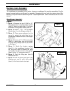
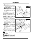
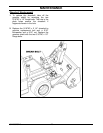
5. Figure 10: Lightly grease the tractor
support arms (item 1).
6. Figure 10: Align the mounting tubes (item
2) with the tractor support arms (item 1)
and slide the snowblower assembly onto
tractor support arms (item 1).
7. Figure 10: Reaching under the tractor,
pull the ring back on the PTO quick
coupler (item 3), slide the coupler onto the
tractor splined shaft, and release the
coupler ring.
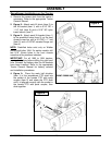
NOTE
: Model MS and earlier Model MC do
not have the PTO quick coupler. Use sliding
joint to connect tractor to snowblower PTO.
IMPORTANT
: To prevent damage to the
machine, make sure the PTO quick coupler is
securely locked on the tractor, with the
locking balls fully seated in the groove and
the ring full forward position. After installation,
pull on the shaft to check for security.
8. Figure 10: Insert the hairpins (item 4) in
the ends of the tractor support arms
(item 1).
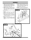
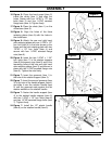
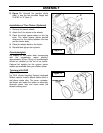
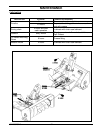
9. Figure 11 Pull the lift handle back
(item 1), press the foot trigger (item 2)
then push the snowblower lift handle
forward against the spring pressure in the
forward position.
10. Figure 11: Remove the 5/16" pin from
each clevis (item 3) and insert the third
link of each chain (item 4) on each clevis
(item 3) as well as a ø1" X 1/16" circle
cotter (item 5).
11. Figure 11: Attach a clevis to each lifting
triangle (item 6) with the 5/16" pin.
12. Figure 11: Lock the clevis pins (item 3) by
inserting one end of each circle cotter
(item 5) in the hole of each clevis pin.
NOTE
: Use a bungee cord or strap to secure
lift handle in forward position while connecting
lift chains to tractor.
CAUTION
: DO NOT release the lift
handle before releasing the foot trigger or
before the snowblower has reached the
DOWN position.
Figure 10
Figure 11