


ASSEMBLY
OM 0352SB-A
11
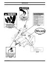
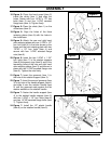
8. Figure 3: Install the pedal stopper (item 1),
the bent portion facing the snowblower and
secure in place with two 1/4"NC x 5/8" hex.
bolts (item 2) and two 1/4"NC serrated
flange nuts (item 3). Tighten firmly.
9. Figure 3: Attach the closed end of the
tension spring (item 4) to the lifting triangle
(item 5). Then, attach the open en of the
tension spring (item 4) to the hole in the
pedal (item 6).
10. Put the snowblower back in its original
position.
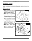
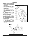
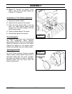
11. Figure 4: Install a 8mm x 7mm x 25mm
key (item 1) on the gearbox shaft (item 7).
12. Figure 4: Slide the male driveline (item 2)
on the gearbox shaft (item 7). The gearbox
shaft (item 7) must be covered by the front
part of the male driveline.
13. Figure 4: Put thread sealant on the
5/16"NC X 3/8" Allen socket setscrew
(item 6) and secure the driveline yoke
(item 2).
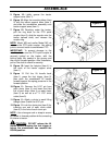
14. Figure 4: Secure the driveline yoke (item
2) to the gearbox shaft (item 7) with a
3/8"NC x 1 3/4" (item 3) hex. bolt, a 3/8"
lockwasher (item 5) and a 3/8"NC nylon
insert nut (item 4). Tighten firmly.
15. Figure 4: Install the two grease fittings
(item 8) on both mounting tubes (item 9).
Figure 4
Figure 3