


ASSEMBLY
OM 0352SB-A
10
SNOWBLOWER ASSEMBLY
The snowblower is assembled at the factory, however, snowblower kits must be assembled. Use the
present manual and lay out all parts for assembly. Separate bolts and nuts into various sizes. After
assembly, torque all the bolts according to the "Torque Specification Table" enclosed at the end of the
manual.
Snowblower Assembly
(Figure 1)
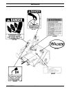
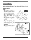
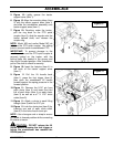
1. Figure 1: Remove the two 5/16"NC x 1/2"
flange bolts (item 1) and the gearbox shield
(item 2). Retain the bolts (item 1) for future
installation of the gearbox shield (item 2).
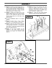
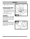
2. Figure 2: Install 1 1/4" x 1/4" flat plastic
handle (item 1) on the lifting arm (item 5).
3. Figure 2: Place some cardboard on the
ground to protect the paint then tip the
snowblower towards the front so the auger
faces down.
4. Figure 2: Insert a ø1" X 1/16" circle cotter
(item 4) in each clevis (item 2) and install
on each lifting triangle (item 6) as shown
on the figure.
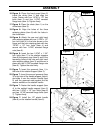
5. Figure 2: Attach the tension springs
(item 3) to the snowblower housing. Pull
the lifting arm (item 5) towards the back
and attach the other end of the springs
(item 3) to the 1/4" clevis pins (item 2).
6. Figure 2: Push the lifting arm (item 5)
towards the front.
7. Figure 2: Lock the clevis pins (item 2) by
inserting one end of each circle cotter
(item 4) in the hole of each clevis pin.
Figure 1
Figure 2