


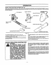

HARDWARE CONTENTS
IL II= IIll II
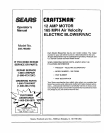
Operator's Manual
III Jllllllll III IL I IIIIIIIIIIIIIIIII IIIIIIII I II UJJ _ .......
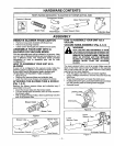
PARTS PACKED SEPARATELY IN CARTON NOT SHOWN ACTUAL SIZE
Concentrator Nozzle
Upper Vacuum Tube
Blower Tube Lower Vacuum Tube
Flare Nozzle
ASSEMBLY
REMOVE BLOWER FR'bM CARTON
- Remove looseparts includedwith Blower/vac.
• Remove all packing material.
• Check carton thoroughly for additional loose parts.
ASSEMBLE YOUR UNIT INTO A
BLOWER OR VACUUM MODE
You can assemble your unit as a blower ora vacuum, Later
you can refer to these instructions and reconfigureyourunit
into a different mode. The instnJctionsbelow provided
information on how to assemble your unit for both
configurations.
HOW TO ASSEMBLE YOUR UNIT AS A
BLOWER
If your unit is configured in the vacuum mode, follow the
following steps to prepare your blower for blower mode.
If your unit is not in the vacuum mode, continue with
"ATTACHING THE BLOWER TUBE & NO_LE."
• Stop the unit.
• Remove the vacuum tubes and collection bag.
• Latch the inlet cover closed, and replace the screw.
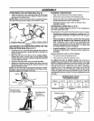
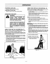
ATTACHING THE BLOWER TUBE & NOZZLE
(Fig. 1, & 2)
Remove the blower vacuum tubes and collection bag, if
assembled to the unit.
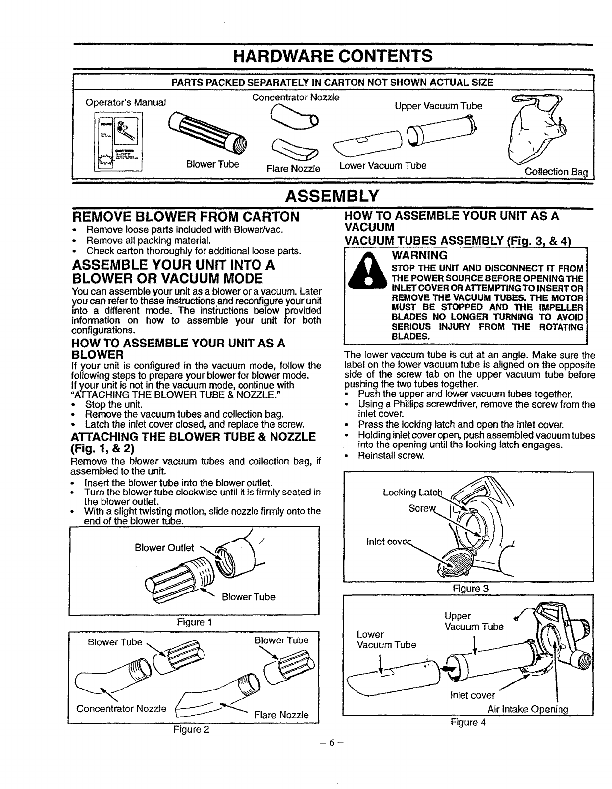
• Insert the blower tube into the bloweroutlet.
• Turn the blowertube clockwise until itis firmly seated in
the blower outlet.
• With a slight twisting motion, slide nozzle firmly onto the
end of the blower tube.
HOW TO ASSEMBLE YOUR UNIT AS A
VACUUM
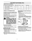
VACUUM TUBES ASSEMBLY (Fig. 3,& 4)
WARNING
STOP THE UNIT AND DISCONNECT IT FROM
THE POWERSOURCE BEFOREOPENING THE
INLETCOVERORATTEMPTINGTO INSERTOR
REMOVE THE VACUUM TUBES. THE MOTOR
MUST BE STOPPED AND THE IMPELLER
BLADES NO LONGER TURNING TO AVOID
SERIOUS INJURY FROM THE ROTATING
BLADES.
The lower vaccum tube is cut at an angle. Make sure the
label on the lower vacuum tube is aligned on the opposite
side of the screw tab on the upper vacuum tube before
pushing the two tubes together.
• Push the upper and lowervacuum tubes together.
o Using a Phillips screwdriver, remove the screw from the
inlet cover.
• Press the locking latch and open the inlet cover.
• Holding inletcover open, push assembled vacuum tubes
into the opening until the locking latch engages.
• Reinstall screw.
Blower Outlet
/
Figure 1
Blower Tube ,. _ Blower Tube
Concentrator Nozzle _""_ Flare Nozzle
Figure 2
Locking Latcb.,.__
Inlet cove,:. _) _/_
Figure 3
Lower
Vacuum Tube
Upper
Vacuum Tube
tnlet cover
Air Intake Openin!
Figure 4
-6-