


R
EPLACING THE TRIMMING LINE
Only use the trimming line described in the Specifications section. Other types of
trimming line may cause the engine to overheat or fail.
NOTE: Always use the correct line length when installing trimming line. The line may
n
ot release properly if the line is too long.
P
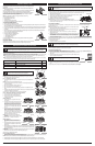
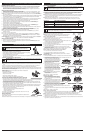
art 1 - Removing the Inner Reel
1
. Hold the outer spool with one hand and unscrew the bump knob counterclockwise
(
Fig. 13).
N
OTE:The outer spool will remain attached to the unit.
2
. Inspect the bolt inside the bump knob to make sure it moves freely. Replace the bump
k
nob if it is damaged.
3
. Remove the inner reel from the outer spool (Fig. 14).
4
. Remove the spring from the inner reel (Fig. 14).
5
. Use a clean cloth to clean the inner reel, spring, shaft and inner surface of the outer
spool.
6
. Check the indexing teeth and holding slots for wear (Fig. 15). If necessary, remove burrs
or replace the inner reel and outer spool.
Proceed to Part 2 - Winding New Trimming Line onto the Inner Reel.
Part 2 - Winding New Trimming Line onto the Inner Reel
• If using single line, refer to Winding Single Line.
• If using split line, refer to Winding Split Line.
• If using a prewound inner reel, proceed to Part 3
- Installing the Inner Reel.
Winding Single Line
1. Cut two 8-foot (2.4 m) lengths of new single
trimming line.
2. Insert the end of one line into the top hole in the
inner reel (Fig. 16). Wind the line tightly in the
direction shown on the bottom of the inner reel
until about 6 inches (150 mm) of line remains.
Keep the line above the split wall. Insert the 6-
inch section into the nearest .095 holding slot
(Fig. 17).
3. Insert the end of the other line into the bottom
hole in the inner reel (Fig. 18). Wind the line
tightly in the direction shown on the bottom of
the inner reel until about 3 to 9 inches (75 to 225
mm) of line remains. Keep the line below the
split wall. Insert the 3 to 9-inch section into the
opposite .095 holding slot (Fig. 19).
NOTE: Failure to wind the line in the direction
indicated will cause the cutting head to operate
incorrectly.
Proceed to Part 3 - Installing the Inner Reel.
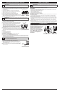
Winding Split Line
1. Cut one 6-foot (1.8 m) length of new split line
trimming line. Split each end about 6 inches (150
mm).
2. Using one split end, insert one line into the top hole
and the other line into the bottom hole in the inner
reel (Fig. 20).
3. Wind the line tightly in the direction shown on the bottom of the inner reel. The split wall will
automatically divide the line. Wind the line until it is completely divided and about 6 inches
(150 mm) of line remains.
NOTE:Failure to wind the line in the direction indicated will cause the cutting head to operate
incorrectly.
4. Insert the two 6-inch sections into the two .095 holding slots (Fig. 21).
Proceed to Part 3 - Installing the Inner Reel.
Part 3 - Installing the Inner Reel
1. Pass the two line ends through the eyelets in the outer spool. Place the spring inside the inner reel. Insert the inner reel into the
outer spool. Push the inner reel and outer spool together (Fig. 22).
NOTE:The spring must be assembled on the inner reel before reassembling the cutting head.
2. While holding the inner reel and outer spool together, firmly pull the two line ends to release them from the holding slots.
3. While holding the inner reel and outer spool together, screw the bump knob on clockwise. Tighten the bump knob securely.
A
IR FILTER MAINTENANCE
Cleaning the Air Filter
F
ailure to maintain the air filter properly can result in poor performance or can cause permanent damage to the engine.
1
. Open the air filter cover by pressing the lock tab in and pulling out on the air filter cover (Fig. 23).
2
. Remove the air filter (Fig. 23).
3
. Wash the filter in detergent and water. Rinse the filter thoroughly and allow it to dry.
4
. Apply enough clean SAE 30 motor oil to lightly coat the filter.
5
. Squeeze the filter to spread and remove excess oil.
6
. Replace the air filter into the air filter cover (Fig. 23).
N
OTE: Operating the unit without the air filter WILL VOID the warranty.
7
. Close the air filter cover by swinging it to the left and then pressing it down until the
l
ock tab snaps into place (Fig. 23).
I
DLE SPEED ADJUSTMENT
T
he idle speed of the engine is adjustable. An idle adjustment screw is between the air filter cover and the engine
s
tarter housing (Fig. 24).
NOTE: Careless adjustments can seriously damage the unit. An authorized service
dealer should make carburetor adjustments.
I
f, after checking the fuel mixture and cleaning the air filter, the engine still will not
i
dle, adjust the idle speed screw as follows:
1
. Start the engine and run for one minute to warm up. Refer to Starting and
Stopping Instructions.
2. Release the throttle trigger and let the engine idle. If the engine stops, insert a small
P
hillips screwdriver into the idle adjustment screw (Fig. 24). Turn the idle speed
s
crew clockwise 1/8 of a turn at a time (as needed) until the engine idles smoothly.
3. If the engine appears to be idling too fast, turn the idle speed screw counterclockwise 1/8 of a turn at a time (as
needed), to reduce idle speed.
C
hecking the fuel mixture, cleaning the air filter and adjusting the idle speed should solve most engine problems. If not
a
nd all of the following are true:
•
the engine will not idle
•
the engine hesitates or stalls on acceleration
•
there is a loss of engine power
H
ave the carburetor adjusted by an authorized service dealer.
R
EPLACING THE SPARK PLUG
U
se replacement #753-06193, a Champion RDJ7J spark plug, or equivalent. The correct air gap is 0.025 inch (0.635 mm).
R
emove the plug after every 25 hours of operation and check its condition.
1
. Stop the engine and allow it to cool. Grasp the plug wire firmly and pull it from the
spark plug.
2.
Clean around the spark plug. Remove the spark plug from the cylinder head by turning
a
5/8-inch socket counterclockwise.
3
. Replace a cracked, fouled or dirty spark plug. Set the air gap at 0.025 in. (0.635 mm)
using a feeler gauge (Fig. 25).
4
. Install a correctly-gapped spark plug in the cylinder head. Tighten by turning the 5/8-inch socket clockwise until
snug.
If using a torque wrench torque to: 110-120 in.•lb. (12.3-13.5 N•m)
Do not over tighten.
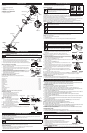
T
he Bump Head™ cutting head allows the release of trimming line without stopping the engine.
T
o release more line, lightly tap the cutting head on the ground (Fig. 11) while operating the unit
a
t high speed.
N
OTE:
A
lways keep the trimming line fully extended. Line release becomes more difficult when
t
he cutting line gets shorter.
E
ach time the head is bumped, about 1 inch (25.4 mm) of trimming line releases. A blade in the
cutting head shield will cut the line to the proper length if any excess line is released.
For best results, tap the bump knob on bare ground or hard soil. If attempting a line release in
tall grass, the engine may stall. Always keep the trimming line fully extended. Line release
becomes more difficult when the cutting line gets shorter.
NOTE:Do not rest the Bump Head™ on the ground while the unit is running.
Some line breakage will occur from:
• Entanglement with foreign matter
• Normal line fatigue
• Attempting to cut thick, stalky weeds
• Forcing the line into objects such as walls or fence posts
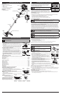
TIPS FOR BEST TRIMMING RESULTS
• Keep the cutting head parallel to the ground.
•
Do not force the cutting head. Allow the tip of the line to do the cutting, especially along walls. Cutting with more than the tip will
reduce cutting efficiency and may overload the engine.
• Cut grass over 8 inches (200 mm) by working from top to bottom in small increments to avoid premature line wear or engine drag.
• Cut from right to left whenever possible. Cutting to the left improves the unit's cutting efficiency. Clippings are thrown away from
the operator.
•
Slowly move the unit into and out of the cutting area at the desired height. Move either in a forward-backward or side-to-side
m
otion. Cutting shorter lengths produces the best results.
• Trim only when grass and weeds are dry.
• The life of the cutting line is dependent upon:
•
Following the trimming techniques
• What vegetation is being cut
• Where vegetation is cut
For example, the line will wear faster when trimming against a foundation wall as opposed to
trimming around a tree.
D
ECORATIVE TRIMMING
D
ecorative trimming is accomplished by removing all vegetation around trees, posts, fences, etc..
R
otate the whole unit so that the cutting head is at a 30° angle to the ground (Fig. 12).
4
WARNING:
To avoid serious personal injury, always turn the unit off and allow it to cool before you
clean or service it.
WARNING:
T
he cutting attachment will spin during idle speed adjustments. Wear protective clothing
and observe all safety instructions to prevent serious personal injury.
WARNING:
Do not sand blast, scrape or clean electrodes. Grit in
t
he engine could damage the cylinder.
Fig. 25
0.025 in.
(0.635 mm.)
F
ig. 23
A
ir Filter Cover
A
ir Filter
L
ock
T
ab
Fig. 24
I
dle Adjustment Screw
MAINTENANCE AND REPAIR INSTRUCTIONS
Fig. 12
OPERATING INSTRUCTIONS
F
ig. 11
Fig. 19
Fig. 21
Fig. 15
Outer Spool
F
ig. 13
Fig. 14
Bump Knob
Fig. 16
Fig. 18
Fig. 20
Holding Slot
Fig. 17
Split Wall
Fig. 22
B
olt
Indexing Teeth
H
olding Slots
O
uter Spool
S
pring
I
nner Reel
Shaft
WARNING:
N
ever use metal-reinforced line, wire, chain or rope.
T
hese can break off and become dangerous projectiles.
Top Hole
Split Wall
Bottom Hole
Split Wall
Holding Slot
Split Wall
Top Hole
Bottom Hole
Split Wall
Holding Slots
Outer Spool
Inner Reel
Bump Knob
Spring
Eyelets
M
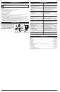
AINTENANCE SCHEDULE
P
erform these required maintenance procedures at the frequency stated in the table. These procedures should also be
a part of any seasonal tune-up.
NOTE: Some maintenance procedures may require special tools or skills. If you are unsure about these procedures, take
your unit to any non-road engine repair establishment, individual or authorized service dealer.
NOTE: Maintenance, replacement, or repair of the emission control devices and system may be performed by any
n
on-road engine repair establishment, individual or authorized service dealer.
N
OTE: Please read the California/EPA statement that came with the unit for a complete listing of terms and coverage
f
or the emissions control devices, such as the spark arrestor, muffler, carburetor, etc.
MAINTENANCE AND REPAIR INSTRUCTIONS
FREQUENCY MAINTENANCE REQUIRED SEE
Before starting engine Fill fuel tank with fresh fuel p. 3
Every 10 hours Clean and re-oil air filter p. 4
Every 25 hours Check spark plug condition and gap p. 4
WARNING:
T
o prevent serious injury, never perform maintenance or repairs with unit running. Always
s
ervice and repair a cool unit. Disconnect the spark plug wire to ensure that the unit cannot start.