


12
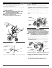
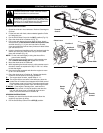
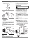
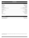
3. Wash the filter in detergent and water (Fig. 20). Rinse the
filter thoroughly and allow it to dry.
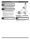
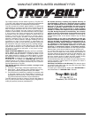
4. Apply enough clean SAE 30 motor oil to lightly coat the
filter (Fig. 21).
Fig. 20
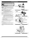
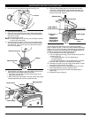
CARBURETOR ADJUSTMENT
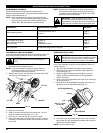
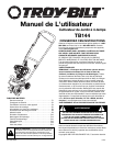
The idle speed of the engine is adjustable. An idle adjustment
screw is reached though a hole in the top of the engine cover
(Fig. 22).
NOTE: Careless adjustments can seriously damage your unit.
For carburetor adjustments, take your unit to a Sears
or other qualified service dealer.
Adjust Idle Speed Screw
If, after checking the fuel and cleaning the air filter, the engine
still will not idle, adjust the idle speed screw as follows:
1. Start the engine and let it run at a high idle for a minute to
warm up. Refer to Starting/Stopping Instructions.
NOTE: Ensure the tines are not in contact with the ground
when adjusting the idle.
2. Release the throttle trigger and let the engine idle. If the
engine stops, insert a small phillips or flat blade screwdriver
into the hole in the air filter/muffler cover (Fig. 22). Turn the
idle speed screw in, clockwise, 1/8 of a turn at a time (as
needed) until the engine idles smoothly.
NOTE: The tines should not rotate when the engine idles.
3. If the tines rotate when the engine idles, turn the idle speed
screw counterclockwise 1/8 of a turn at a time (as needed),
to reduce idle speed.
Checking the fuel, cleaning the air filter, and adjusting the idle
speed should solve most engine problems. If not and all of the
following are true:
• the engine will not idle
• the engine hesitates or stalls on acceleration
• there is a loss of engine power
Have the carburetor adjusted by a Troy-Bilt or other qualified
service dealer.
Fig. 21
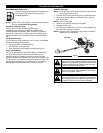
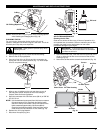
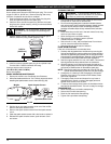
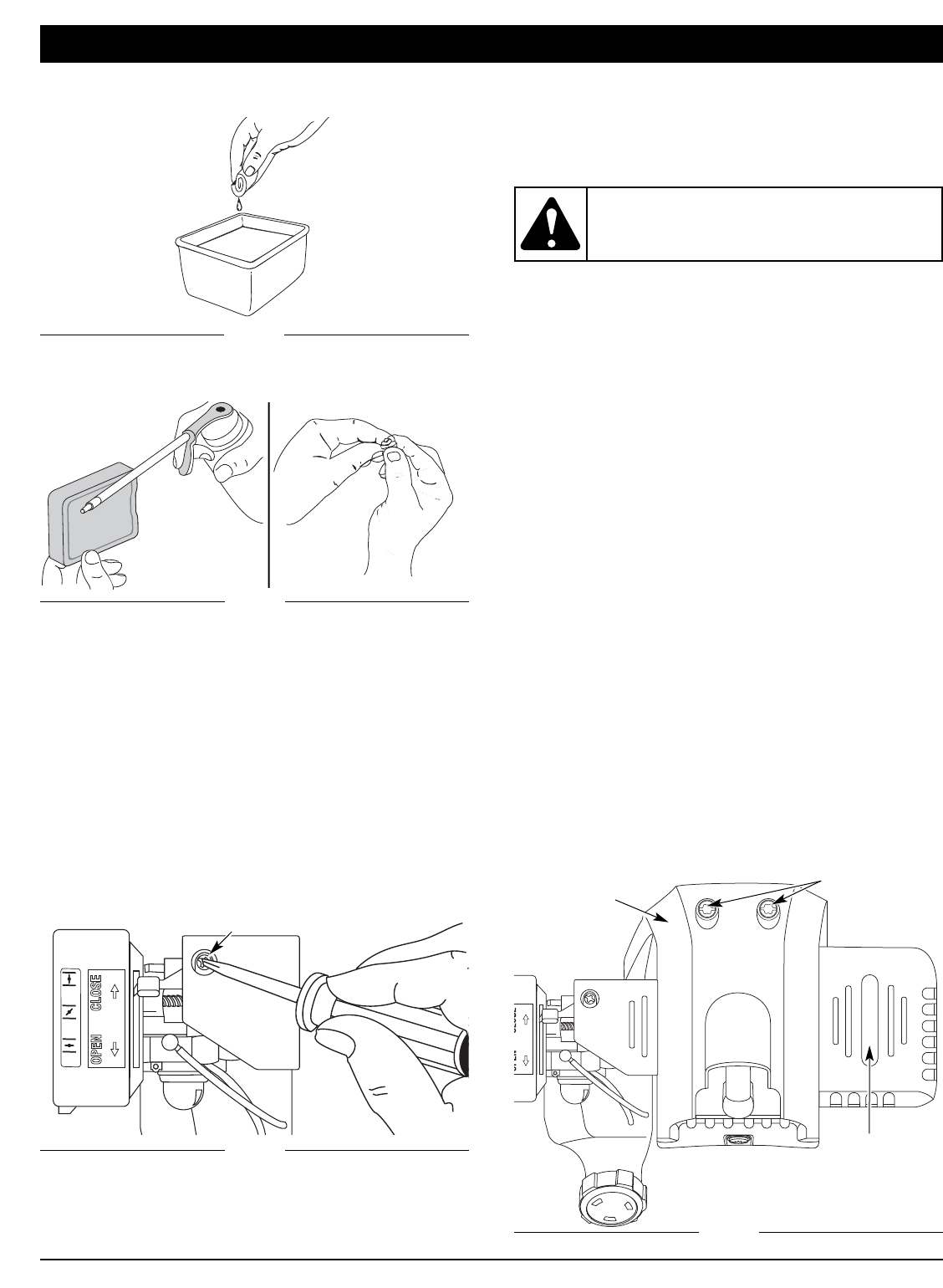
Remove
Screws
Engine Cover
Fig. 23
Muffler
ROCKER ARM CLEARANCE
This requires disassembly of the engine. If you feel unsure or
unqualified to perform this, take the unit to a Sears or other
qualified service dealer.
NOTE: Inspect the valve to rocker arm clearance with a feeler
gauge after the first 10 hours of operation and then
every 25 hours of operation thereafter.
• The engine must be cold when checking or adjusting the
valve clearance.
• This task should be performed inside, in a clean, dust free area.
1. Remove the two (2) screws on top of the engine cover with
a Flat-head or T-25 Torx screwdriver (Fig. 23).
Top View Of The Engine
1
23
Idle Adjustment Screw
Fig. 22
MAINTENANCE AND REPAIR INSTRUCTIONS
WARNING: This unit needs to run during idle
speed adjustment. Wear protective clothing and
observe all safety instructions to prevent serious
personal injury.
5. Squeeze the filter to spread and remove excess oil (Fig. 21).
6. Replace the filter (Fig. 19).
NOTE: If the unit is operated without the air filter, you will VOID
the warranty.
7. Reinstall the air filter cover. Position the hooks on the right
side of the air filter cover into the slots at the right side of
the air filter housing.
8. Swing the cover to the left until the tab on the air filter cover
snaps into place in the slot on the left side of the air filter
housing (Fig. 18).
Check Fuel
Old fuel is usually the reason for improper unit performance.
Drain and refill the tank with fresh fuel prior to making any
adjustments. Refer to Oil and Fuel Information.
Clean Air Filter
The condition of the air filter is important to the operation of the unit.
A dirty air filter will restrict air flow. This is often mistaken for an out of
adjustment carburetor. Check the condition of the air filter before
adjusting the idle speed screw. Refer to Air Filter Maintenance.