


6
3
Setting Up
Your Snow
Thrower
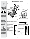
References to the right
or left side of the snow
thrower are determined
from behind the unit in
the operating position
(standing directly behind
the snow thrower, facing
the handle panel).
This Operator’s Manual may cover a range of product
specifications for various models. Characteristics and
features discussed and/or illustrated in this manual may
not be applicable to all models.
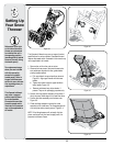
1. Remove the unit from the crate or carton.
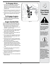
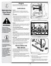
2. Observe the lower area of the snow thrower to be
sure cables are aligned with roller guides before
pivoting handle upward.
a. Pull up and back on upper handle as shown in
Figure 3-1. Align upper handle with the lower
handle.
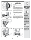
b. Tighten star knobs to secure upper handle to
lower handle, Figure 3-2.
c. Remove and discard any rubber bands, if
present. They are for packaging purposes only.
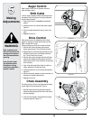
3. Certain units may require assembly of the chute. If
this is the case, follow steps 4-6 to install the chute.
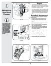
4. Position the chute assembly over the base, see
Figure 3-3.
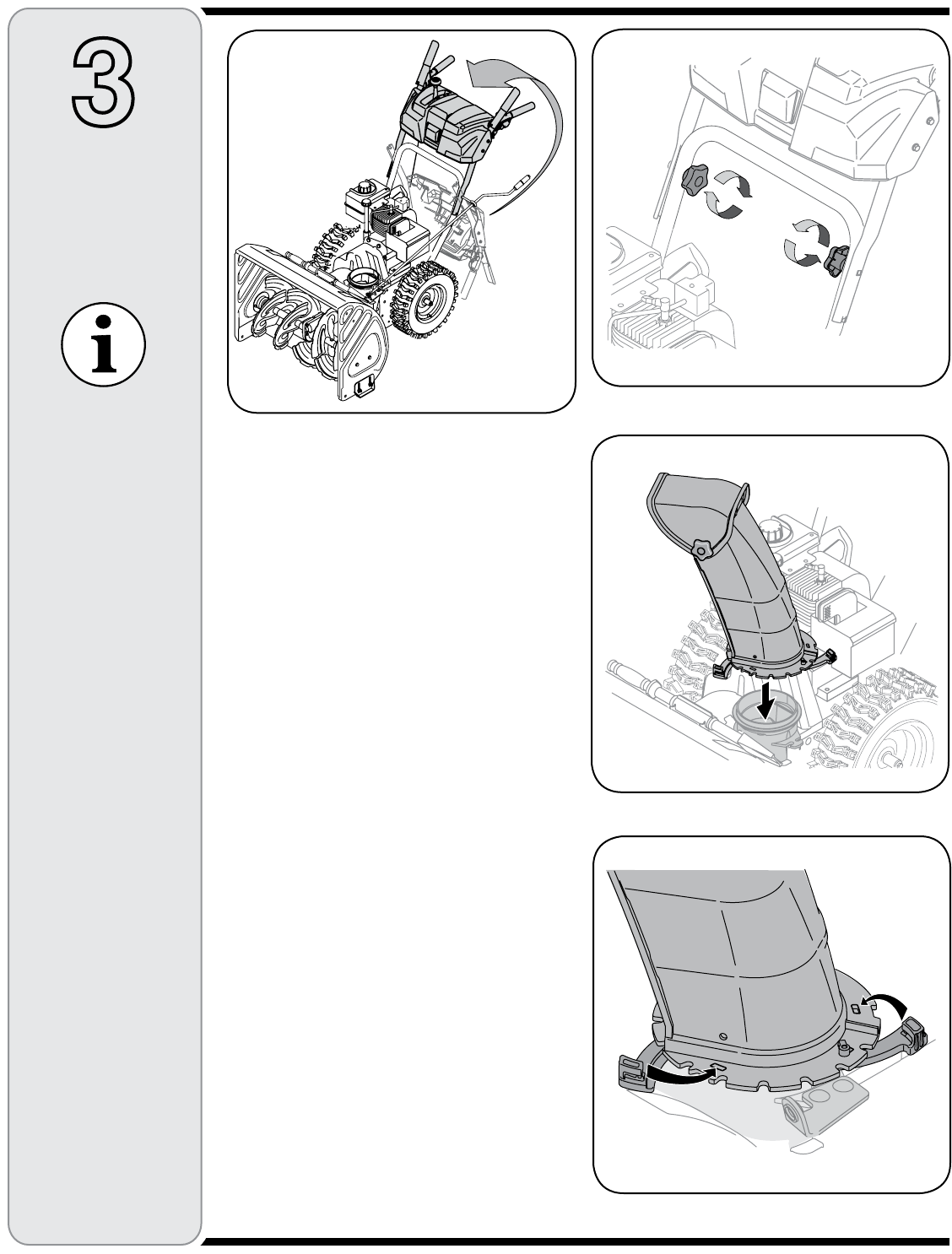
5. Close the flange keepers to secure the chute
assembly to the chute base. The flange keepers will
click into place when properly secure, Figure 3-4.
NOTE: If the flange keepers will not easily click into
place, use the palm of your hand to apply swift, firm
pressure to the back of each.
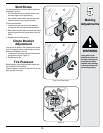
Two replacement auger
shear pins are included
with this manual (or
stowed in the plastic
handle panel). Refer to
Augers in Maintenance
section for more informa-
tion regarding shear pin
replacement.
This Operator’s Manual
may cover a range of
product specifications
for various models.
Characteristics and fea-
tures discussed and/or
illustrated in this manual
may not be applicable to
all models.
Figure 3-1
Figure 3-2
Figure 3-3
Figure 3-4