


14
6
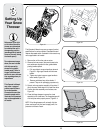
Maintaining
Your Snow
Thrower
WARNING
Before lubricating,
repairing, or inspecting,
disengage all controls and
stop engine. Wait until all
moving parts have come
to a complete stop.
Avoid oil spillage on
rubber friction wheel and
aluminum drive plate.
Engine
Refer to the separate Tecumseh Engines manual
packed with your unit for all engine maintenance.
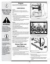
Lubrication
Engine
Refer to the separate Tecumseh Engines manual
packed with your unit for all engine lubrication instruc-
tions.
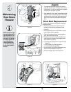
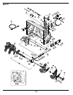
Gear Shaft
The gear (hex) shaft should be lubricated at least once
a season or after every 25 hours of operation.
1. Remove the lower frame cover by removing the two
screws which secure it.
2. Apply a light coating of an all-weather multi-purpose
grease to the hex shaft, Figure 6-1.
Wheels
At least once a season, remove both wheels. Clean and
coat the axles with a multipurpose automotive grease
before reinstalling wheels.
Chute Directional Control
Once a season, the joystick should be lubricated with
petroleum jelly, linseed oil, mineral oil, paraffin wax, or
3-in-1 oil.
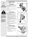
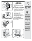
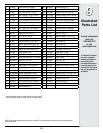
Auger Shaft
At least once a season, remove the shear pins on auger
shaft. Spray lubricant inside shaft, around the spacers.
Also lubricate the flange bearings found at either end of
the shaft, Figure 6-2.
Gear Case
The auger gear case has been filled with grease at the
factory. If disassembled for any reason, lubricate with
two ounces of grease (Part Number 737-0168).
NOTE: Do not overfill the gear case. Damage to the
seals could result. Be sure the vent plug is free of
grease in order to relieve pressure.
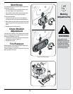
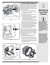
Shave Plate and
Skid Shoes
The shave plate and skid shoes on the bottom of the
snow thrower are subject to wear. They should be
checked periodically and replaced when necessary.
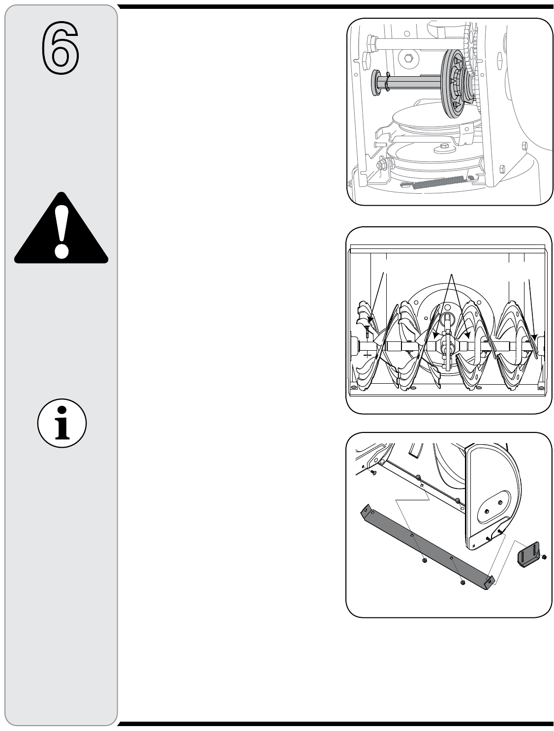
To remove skid shoes:
1. Remove the four carriage bolts and hex flange nuts
which secure them to the snow thrower.
2. Reassemble new skid shoes with the four carriage
bolts (two on each side) and hex flange nuts, Figure
6-3.
Do not overfill the gear
case. Damage to the seals
could result.
Figure 6-1
Figure 6-2
3HEAR0IN
"EARING
3PACERS
Figure 6-3
./4%!UGERSNOTSHOWNFORCLARITY
To remove shave plate:
1. Remove the carriage bolts and hex nuts which attach
it to the snow thrower housing.
2. Reassemble new shave plate, making sure heads of
carriage bolts are to the inside of housing. Tighten
securely.
This Operator’s Manual
may cover a range of
product specifications for
various models. Char-
acteristics and features
discussed and/or
illustrated in this manual
may not be applicable to
all models.