


WARNING! To prevent personal injury or property
damage, do not start the engine until all assembly
steps are complete and you have read and
understand the safety and operating instructions.
Recommended Tools for Assembly
⁄” open-end wrench
⁄” open-end wrench
⁄” open-end wrench
Scissors (to trim plastic ties)
Ruler
Small board (to tap plastic knob on lever)
Tire pressure gauge
Clean oil funnel
Clean, high-quality motor oil. Refer to the separate
Engine Operator’s Manual for motor oil specifications and
quantity.
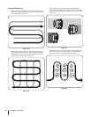
Contents of Hardware pack
⁄-16 x 1” Hex Hd. Screw (2)
Keyed Washer (1)
Wheel Gear Lever Knob (1)
Height Adjustment Flange Screw (1)
⁄” Flat Washer (2)
#10 Lockwasher (2)
⁄”-16 Nylock Lock Nut (2)
#10-32 x ⁄” Round Hd. Screw (2)
#10-32 Nut (2)
Cotter Pin (1)
Cable Tie (4)
Assembly
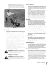
Unpacking Instructions
Remove any cardboard inserts and packaging material
from the carton. Remove any staples from the bottom of
the carton and remove the carton.
Cut the large, plastic tie strap that secures the transmission
tube to the shipping pallet. Leave the handlebars on top of
the tiller to avoid damaging any cables.
The hardware pack is is inside the literature envelope.
Check the contents with the list above.
•
•
•
•
•
•
•
•
•
•
•
•
•
•
•
•
•
•
•
•
1.
2.
3.
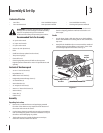
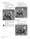
The tiller is heavy. You should not attempt to remove it
from the shipping platform until instructed to do so in
these steps.
Handle
Cut the large, plastic cable ties that secure the handlebar
ends to the handlebar mounting tabs on the transmission
top cover.
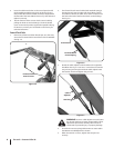
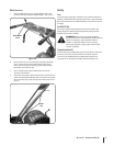
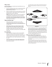
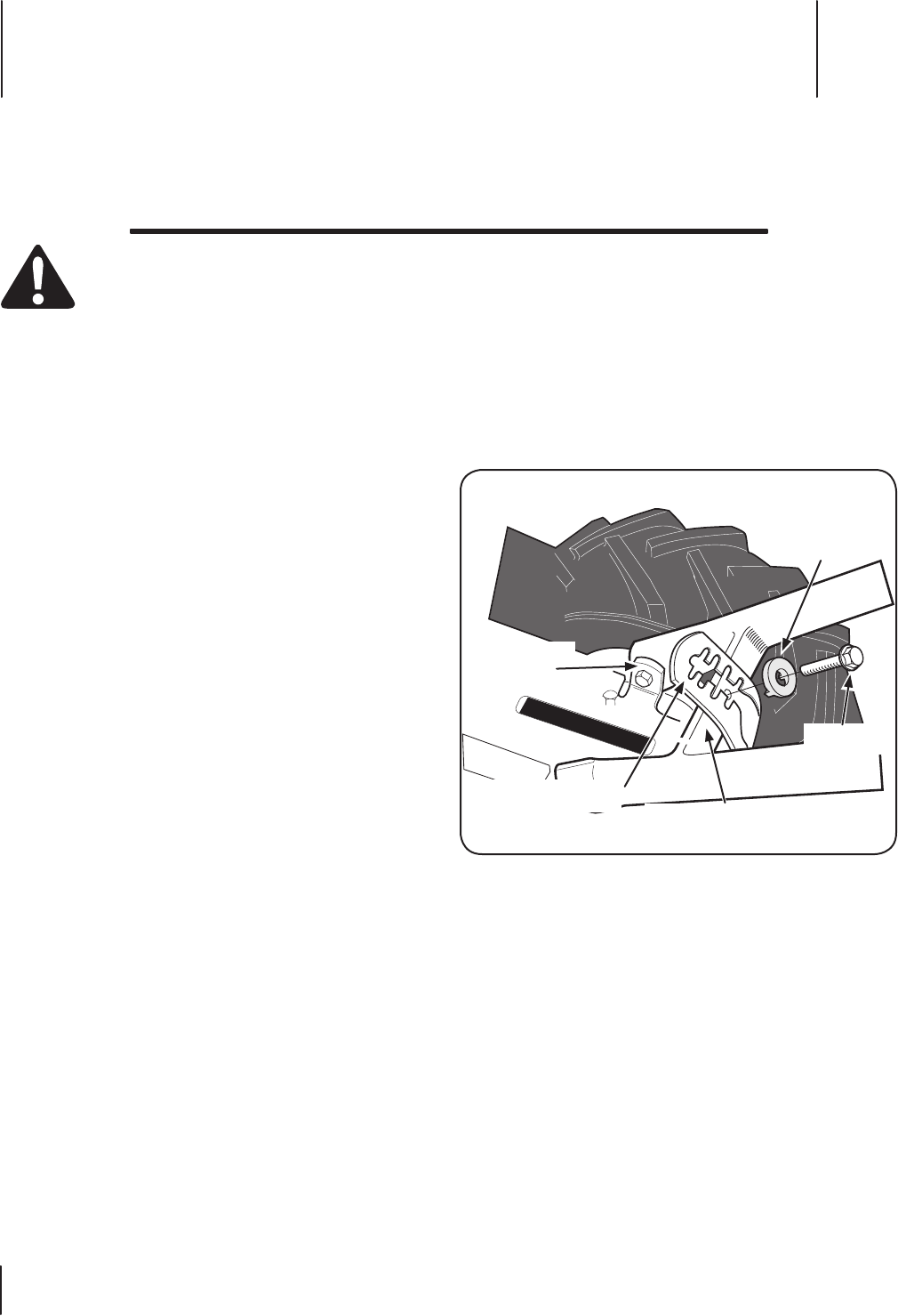
Gently lift the handlebar (do not overstretch the attached
cable) and place the handlebar cross-brace in front of the
curved height adjustment bracket. See Fig. 3-1.
4.
1.
2.
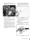
shown for clarity.
Height Adjustment
Bracket
Handlebar Cross Brace
Keyed
Washer
Adjustment
Screw
Mounting
Tabs
Figure 3-1
Contents of Carton
One Tiller • One Handlebar Support• One Handlebar Assembly•
One Hardware Pack• One Operator’s Manual• One Engine Operator’s Manual•
Assembly & Set-Up
3
6