


9Section 2 — ASSembly & Set-Up
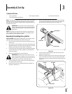
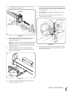
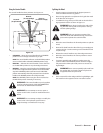
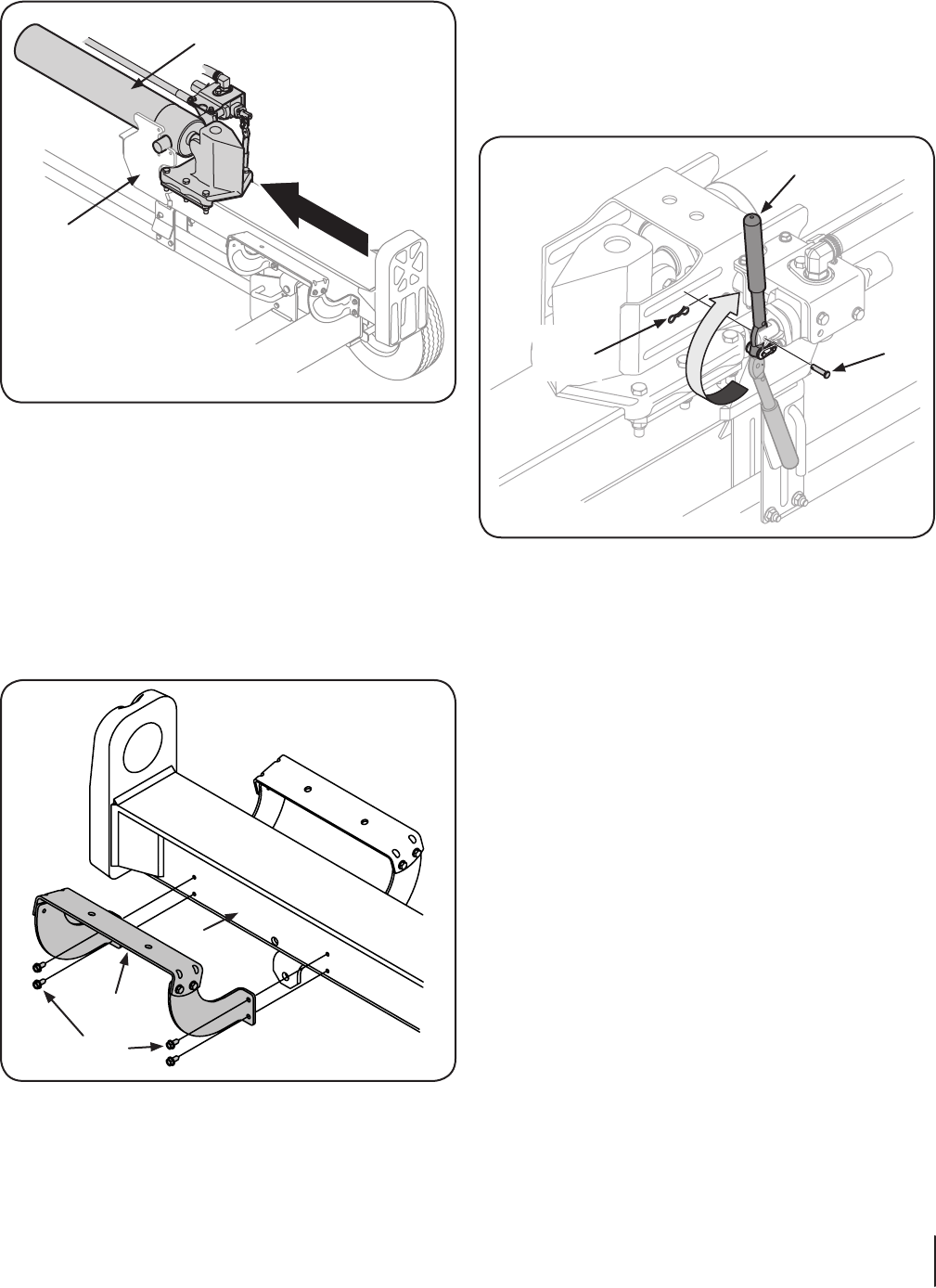
16. Lift and slide the cylinder up to the top of beam and into
the weld brackets. See Figure 3-6.
Cylinder
Weld Brackets
Figure 3-6
17. Attach the dislodger over the wedge assembly and secure
it to the weld brackets with the previously removed
hardware. See Figure 3-4.
NOTE: Lift up on the cylinder when installing the hex screws.
NOTE: Once the six hex screws are tightened, there may be
a slight gap between the dislodger and the weld brackets.
This gap is normal.
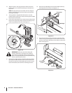
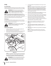
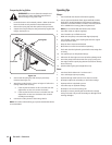
18. Reattach the log tray to the side of the beam with the
control valve, aligning the holes in the tray with the holes
in the beam. See Figure 3-7.
Hex Washer
Screw
Log Tray
Beam
Figure 3-7
19. Check for and remove any staples on the bottom of the
crate that may puncture the tire.
20. Cut the metal strap securing the log splitter to the bottom
of the crate and remove the wood under the engine and/or
any other wood, then roll the log splitter off the bottom of
the shipping crate.
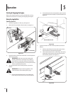
21. The control handle is shipped hanging from the valve on
the handle link.
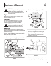
22. Remove the clevis pin and bow-tie cotter pin from the
control handle. See Figure 3-8.
Bow-Tie
Cotter
Pin
Control Handle
Clevis
Pin
Figure 3-8
23. Rotate the control handle into the operating position and
secure with the clevis pin and bow-tie cotter pin removed
in step 1. See Figure 3-8.