


Se rvice
7
17
Flexible Pump Coupler
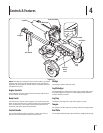
The flexible pump coupler is a nylon “spider” insert, located
between the pump and the engine shaft. Over time, the coupler will
harden and deteriorate. Replace the coupler if you detect vibration
or noise coming from the area between the engine and the pump. If
the coupler fails completely, you will experience a loss of power.
NOTE: On vertical shaft engines, it will be neccessary to remove
the engine to access the hex screws securing the pump to the
engine shaft. Taking the log splitter to an authorized service
dealer is recommended.
NOTE: Never hit the engine shaft in any manner, as a blow will
cause permanent damage to the engine.
1. Disconnect the spark plug wire and ground it against the
engine.
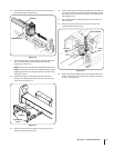
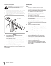
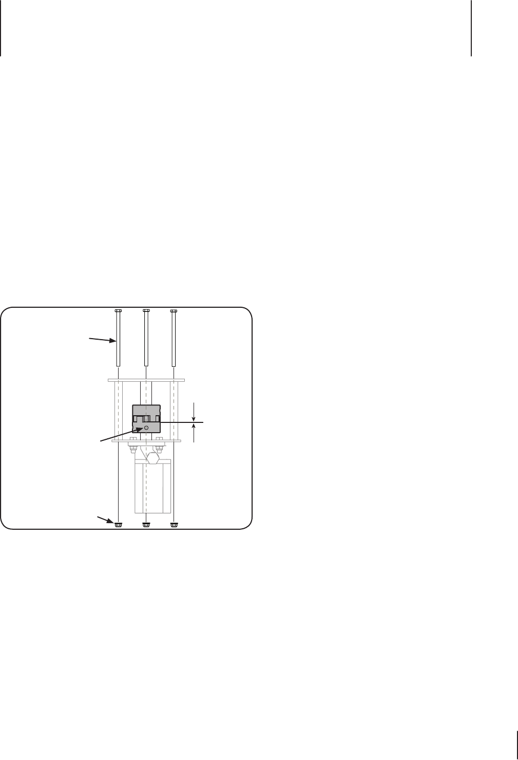
2. Remove the three flange lock nuts and hex screws that
secure the pump to the coupling shield. Two flange lock
nuts and hex screws are at the bottom corners and one is in
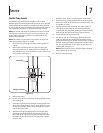
the top center. See Figure 7-1
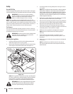
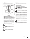
.090
.020
Flange Lock Nuts
Hex Screw
Set Screw
Figure 7-1
3. Remove the pump.
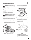
4. Loosen the set screw on the pump coupling half and remove
the coupling half.
5. Rotate the engine by slowly pulling the starter handle until
the engine coupling half set screw is at the bottom. Loosen
the set screw using an allen wrench and slide the coupling
half off the engine shaft.
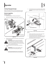
6. Slide the new engine coupling half onto the engine shaft
until the end of the shaft is flush with the inner portion of
the coupling half. (There must be space between the end of
the engine support bracket and the coupling half). Tighten
the set screw.
7. Install the nylon “spider” onto the engine coupling half.
8. Install the pump coupling half and key on the pump shaft.
Rotate the coupling half until the set screw faces down. Do
not tighten set screw.
9. Align the pump coupling half with the nylon “spider” by
rotating the engine using the starter handle. Slide the
coupling half into place while guiding the three mounting
bolts through the holes in the pump support bracket.
10. Secure with the nuts removed earlier.
11. Set .020” to .090” of a clearance/gap between the nylon
“spider” and the engine coupling half by sliding a feeler
gauge between the nylon “spider” and the engine coupling
half and moving the pump coupling half as needed. Install
the set screw and torque to 78 in-lbs to secure the pump
coupling half. See Figure 7-1.
NOTE: Make certain the proper clearance/gap is obtained
before tightening the set screw.
12. Reconnect the spark plug.