


21
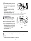
5. Remove the upper drive belt by pulling it up through the battery tray opening.
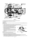
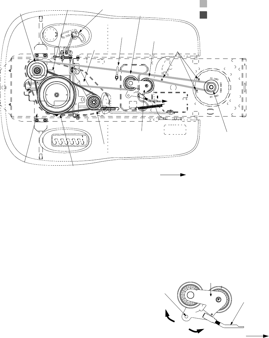
6. Reroute the new upper drive belt as shown in Figure 16.
Lower Drive Belt
IMPORTANT:
Note the routing of the lower drive belt around both the pulleys and the belt keepers before performing
the following steps.
1. Locate the variable-speed pulley through the battery tray opening. See Figure 16.
2. Remove the variable-speed pulley by loosening the hex bolt that secures it to the transmission. Use a second
wrench to hold the hex nut on the bottom side of the pulley.
3. Slide the belt off the variable-speed pulley as you lift the
pulley up and out through the battery tray opening.
4. Remove the rear idler pulley from the double-idler bracket
while unrouting the belt from around both the rear and the
front idler pulley. See Figure 16.
5. Remove the hex bolt from the center of the engine pulley
and gently lower it off the engine crankshaft. Be careful not
to lose any washers or spacers which may be on top of the
engine pulley.
IMPORTANT:
When remounting the engine pulley, torque the
center hex bolt to between 38 and 50 foot-pounds.
6. Remove drive belt by feeding it from both ends toward the
front idler pulley on the double-idler bracket. See Figure 16.
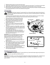
7. Reassemble by following the above steps in reverse order. Reroute the new belt around the pulleys, belt
keepers and keeper pins exactly as the old one was routed. Refer to Figure 16.
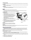
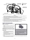
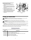
• The drive pedal is properly adjusted when the hole in the double-idler bracket has approximately 1-3/8" of travel
with 10 lbs. pressure applied to the drive pedal. See Figure 17.
Drive belt (Lower)
Drive belt (Upper)
Front of Tractor
Rear Idler Pulley
Front Idler Pulley
Variable-Speed
Pulley
Battery Tray
Keeper Pins
Transmission Idler Pulley
Transmission Pulley
Engine Pulley
Single-Speed
Transmission
Shift Lever
Opening
Double-Idler Bracket
Idler Bracket
to drive pedal
Belt Keeper
NOTE:
View shown from above tractor.
Figure 16
Double-Idler
Bracket
Idler
Adjuster Rod
Hole
1
-
3
/
8
”
Front of Tractor
NOTE:
View shown from above tractor.
Figure 17