


Adjusting Reverse Drive:
1. Place Wheels/Tines/PTO Drive Lever in
FORWARD position.
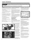
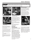
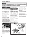
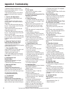
2. On left side of tiller, put a 1/2" wrench
on the plunger retaining bolt and another
1/2" wrench on the jam nut next to it
(Figure 5-27). While holding the bolt
steady, loosen the jam nut (counterclock
-
wise) until it touches the bolt head.
3. Turn the bolt in until it tightens against
the plunger inside the spring. The bolt
must be tight to prevent plunger from
turning – but be careful not to overtighten
and break the bolt.
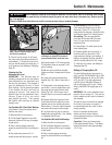
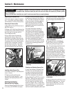
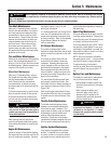
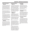
4. Place a 7/8" wrench on the head of
the reverse adjustment bolt and a 9/16"
wrench on the jam nut below it (Figure 5-
28). Hold the bolt steady while loosening
the jam nut three or four turns.
5. Move the Wheels/Tines/PTO Drive
Lever to NEUTRAL. The switch body
on the bottom of the engine mount tab
(Figure 5-24) should be resting squarely
on top of the reverse adjustment bolt, and
the reverse disc should be at least 3/16"
away from the transmission drive pulley.
If the reverse disc is any closer than this,
raise the reverse adjustment bolt (turn it
counterclockwise).
6. Check that reverse disc is at least 3/16"
away from transmission drive pulley.
Then hold reverse adjustment bolt steady
with one wrench while tightening jam nut
with a second wrench (Figure 5-28).
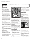
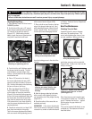
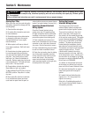
7. Place a chalk or pencil mark on the top
edge of the plunger retaining bolt. Now,
while watching the mark, loosen the bolt
3/4-turn (Figure 5-29). Do not exceed a
3/4 turn (this would disengage the bolt
from the locking groove in the side of the
plunger).
8. Hold the plunger retaining bolt steady
with a wrench while tightening the jam
nut against the side of the plunger housing
(Figure 5-27).
9. Check the action of the reverse disc as
explained previously.
IMPORTANT: If the above adjustments
have not corrected an improperly working
reverse drive, contact an authorized dealer
or Factory Technical Service Department
for assistance.
Bolo Tine Maintenance
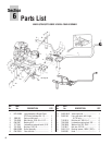
Checking Tines for Wear
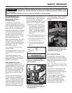
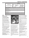
Inspect the tines for wear or damage
after every 30 operating hours. The
rate of wear depends upon hours of use
and soil conditions. With use, the tines
get shorter, narrower and more pointed
(Figure 5-30). If badly worn, they lose the
ability to till deeply.
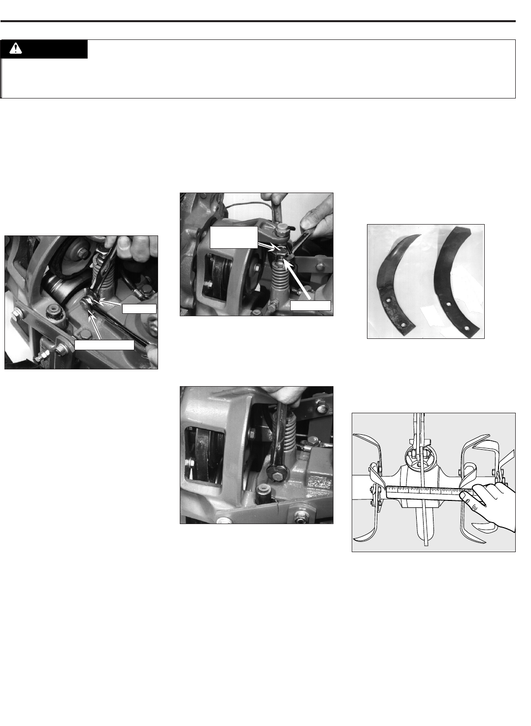
Worn tines leave an ever-increasing gap
in the middle of a tilled row. The normal
gap is 3" between the tine tips – replace
the tines when the gap widens to 5"
(Figure 5-31).
Tines can be replaced individually or as a
complete set. See replacement instruc-
tions that follow.
Figure 5-29: Loosen plunger
retaining bolt about 3/4-turn, then
tighten jam nut against plunger
housing.
Figure 5-31: Replace tines when gap
between inner tines is 5" or more
(normal gap is 3").
1
2
3
4
5
6
7
8
Figure 5-30: Check for wear
every 30 operating hours.
Worn New
Figure 5-27: Hold bolt steady while
loosening or tightening jam nut.
Retaining Bolt
Jam Nut
Section 5: Maintenance
Before inspecting, cleaning or servicing the machine, shut off engine, wait for all moving parts to come
to a complete stop, disconnect spark plug wire and move wire away from spark plug. Remove ignition
key, if so equipped.
Failure to follow these instructions can result in serious personal injury or property damage.
WARNING
Figure 5-28: Loosen jam nut before
turning reverse adjustment bolt.
Adjustment
Bolt
Jam Nut
37