


11
• When sharpening blades, follow the original angle
of grind. Also, make sure to remove an equal
amount from each blade and torque hardware to
250 - 300 in.lb.
NOTE: Make sure that blades are reassembled with the
sharp edge facing upward.
Replacing the Belt
NOTE: Because the engine on this equipment has a
tapered crankshaft, a special impeller removal tool (part
number 753-0900) is required to remove the impeller
assembly. Contact your local service dealer for this.
• Disconnect the spark plug wire and ground it away
from the spark plug.
• Drain the gasoline and oil from the chipper
shredder vacuum.
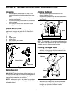
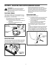
• Remove the three wing nuts that secure the nozzle
to the outer housing and remove the nozzle. Refer
to Figure 2.
• Remove the vacuum bag from the unit.
• Remove the discharge chute as instructed in
“Cleaning The Flail Screen.”
• Remove the plastic belt cover from front of the
engine by removing two self-tapping screws. Refer
to Figure 13.
• Tip the unit backward so that it rests on the
handles.
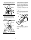
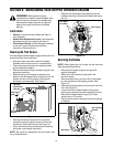
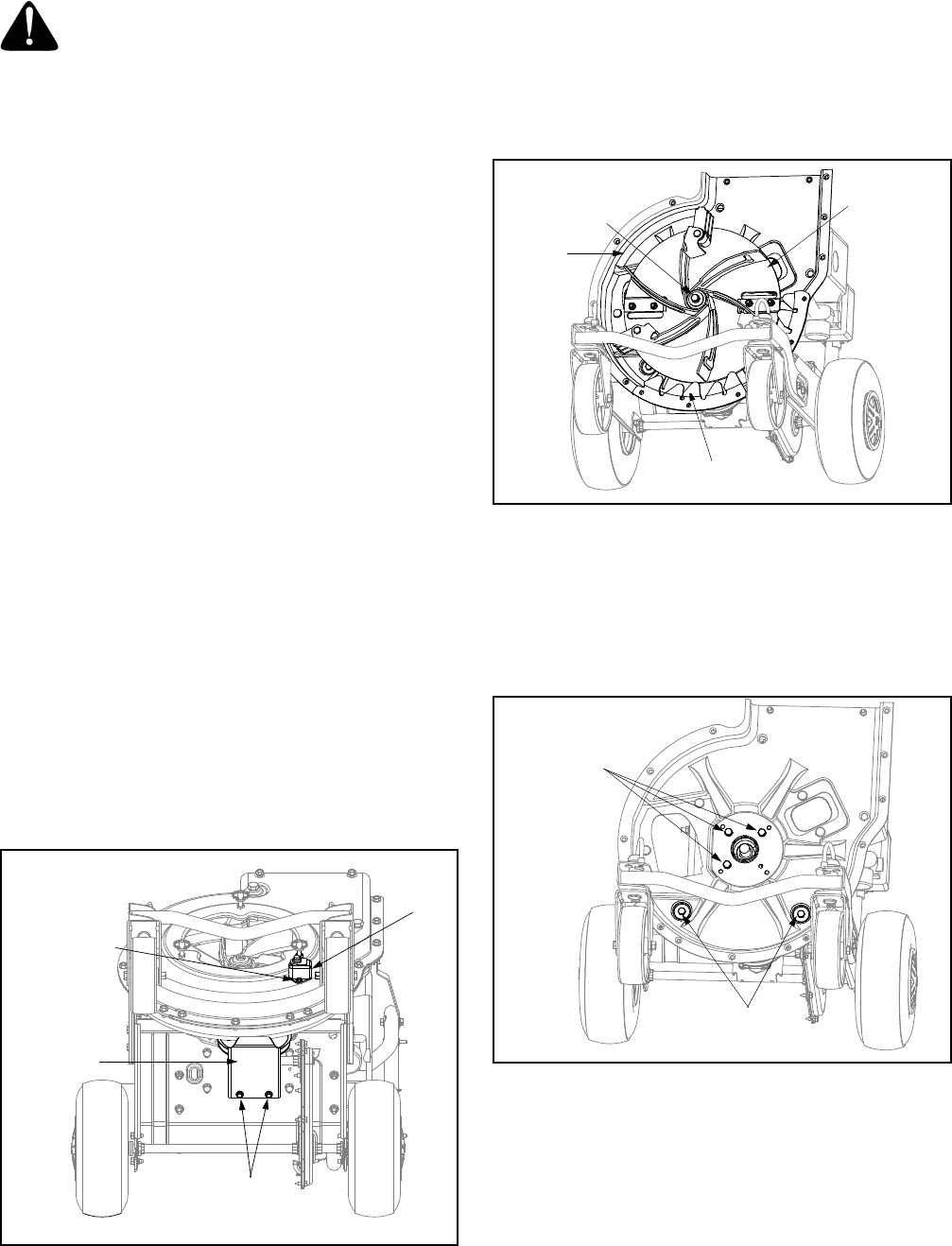
• Remove the lower belt guard by removing the two
self-tapping screws. See Figure 14.
• Remove the safety switch from front of the outer
housing by removing the two self-tapping screws.
See Figure 14.
Figure 14
• Remove the two hex bolts and hex lock nuts which
extend through the housing. Lift the flail screen out
of the housing. Refer to Figure 11.
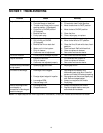
• Remove the outer housing and housing blades by
removing the fourteen self-tapping screws.
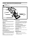
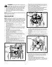
• Remove the hex bolt, lock washer, and flat washer
that secures the impeller assembly to the
crankshaft. See Figure 15.
Figure 15
• Thread the special impeller tool into the crankshaft.
Stop when the impeller assembly can move on the
crankshaft.
• If the old belt is still on the unit, cut belt to remove
from unit.
• Remove impeller assembly from the crankshaft and
unthread the impeller tool from the impeller.
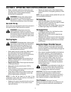
Figure 16
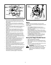
• Remove the inner housing and mounting adapter
by removing the five hex bolts and two hex nuts.
See Figure 16.
• Insert new belt between the frame and the
transmission pulley. See Figure 17. (You may have
to slightly pry the frame away from the pulley with a
screwdriver for this.)
WARNING: Use caution when replacing the
blades. Wear heavy gloves to avoid injury while
handling the weld bolts, housing or the blades.
Safety
Switch
Self-Tapping
Screw
Lower
Belt Guard
Self-Tapping
Screws
Impeller
Assembly
Hex Bolt
Lock Washer
Flat Washer
Inner
Housing
Housing
Blades
Hex Bolts
Hex Bolts