


9
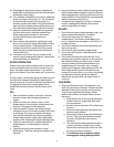
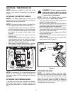
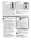
Quick Adjustment Seat
NOTE: If your seat was shipped mounted backwards
on the seat pivot bracket, pull out the tab found on the
seat stop and hold it open while sliding the seat off the
seat pivot bracket. See Figure 3 .
1. Line up the plastic seat spacers with the slots in
seat pivot bracket.
2. Slide seat in until front seat spacer engages the
seat stop.See Figure 3 .
WARNING: Before operating this machine,
make sure the seat is engaged in the seat
stop, stand behind the machine and pull back
on seat until fully engaged into stop
.
Figure 3
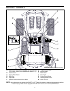
GAS AND OIL FILL-UP
The gasoline tank is located under the hood and has a
capacity of either two or three gallons. Do not overfill.
WARNING: Use extreme care when
handling gasoline. Gasoline is extremely
flammable and the vapors are explosive.
Never fuel machine indoors or while the
engine is hot or running. Extinguish
cigarettes, cigars, pipes, and other sources of
ignition.
Service the engine with gasoline and oil as
instructed in the separate engine manual packed
with your tractor. Read instructions carefully.
IMPORTANT: Your tractor is shipped with oil;
however, you MUST check the oil level before
operating. Be careful not to overfill. Overfilling with oil
may cause the engine to smoke. This will result in poor
engine performance and could cause permanent
engine damage.
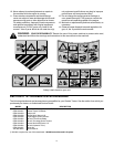
WARNING: The mowing deck is capable of
throwing objects. Failure to operate the riding
mower without the discharge cover in the
proper operating position could result in
serious personal injury and/or property
damage.
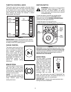
TIRE PRESSURE
WARNING: Maximum tire pressure under
any circumstances is 30 p.s.i. Equal tire
pressure should be maintained at all times.
The tires on your unit may be over-inflated for shipping
purposes. Reduce the tire pressure before operating
the tractor. Recommended operating tire pressure is
approximately 10 p.s.i for the rear tires & 14 p.s.i. for
the front tires. Check the sidewall of tire for maximum
p.s.i.
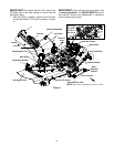
ATTACHING THE CUTTING DECK 54”
DECK
WARNING: Before attaching the cutting
deck, engage the parking brake, turn the
ignition key to the OFF position and remove
the key from the switch to avoid accidental
starting.
• Adjust the deck roller height so that the clevis pins
are inserted in the second hole (from the top) of
both the left-hand deck roller bracket and the right-
hand deck roller bracket. See Figure 4 or refer to
Deck Roller Height Adjustment .
• Raise the deck lift arms up and out of the way by
placing the deck lift lever in the top notch on the
right fender.
• Gently slide the cutting deck beneath the tractor
from the right side.
• Move the cutting deck into position so that the
hooks found on the front end of the deck fit snugly
around the deck stabilizer rod as shown in Figure 4.
NOTE: The stabilizer rod may be secured to the
tractor frame with a plastic cable tie for shipping
reasons. If so, carefully cut the cable tie before
mounting the front of the cutting deck.
• Lower the deck lift arms by placing the lift lever in
the bottom notch on the right fender.
• Pull the deck support pin (on the left side of the
deck) outward and align it with the hole on the rear
of the left deck lift arm before releasing the pin to
lock it in place as shown in Figure 4. Repeat on the
right side.
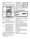
INSTALLING THE PTO/DECK BELT
• Make certain that the PTO/Deck belt is routed
around the spindle pulleys (found beneath the belt
guards) and both idler pulleys as illustrated in inset
in Figure 4 before proceeding.
• Insert a 3/8” drive ratchet wrench (set to “loosen”)
into the hole on the idler bracket and pivot the
wrench handle clockwise. This will relieve the
tension on the deck idler.
Quick Adjustment
Seat Stop
Tab
Pivot Bracket