


19
measurements taken should be equal. If they’re
not, proceed to the next step.
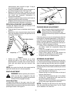
• Loosen, but do NOT remove, the hex cap screw on
the left deck hanger bracket. See Figure 10B.
• Balance the deck by using a wrench to turn the
adjustment gear (found immediately behind the hex
cap screw just loosened) clockwise/up or
counterclockwise/down.
• The deck is properly balanced when both blade tip
measurements taken earlier are equal.
• Retighten the hex cap screw on the left deck hanger
bracket when proper adjustment is achieved.
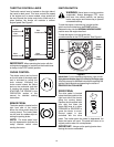
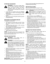
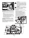
DECK ROLLER HEIGHT ADJUSTMENT
To adjust the height of the rollers on the rear of the
mowing deck, proceed as follows:
• Place the deck lift lever in the bottom notch (lowest
position).
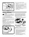
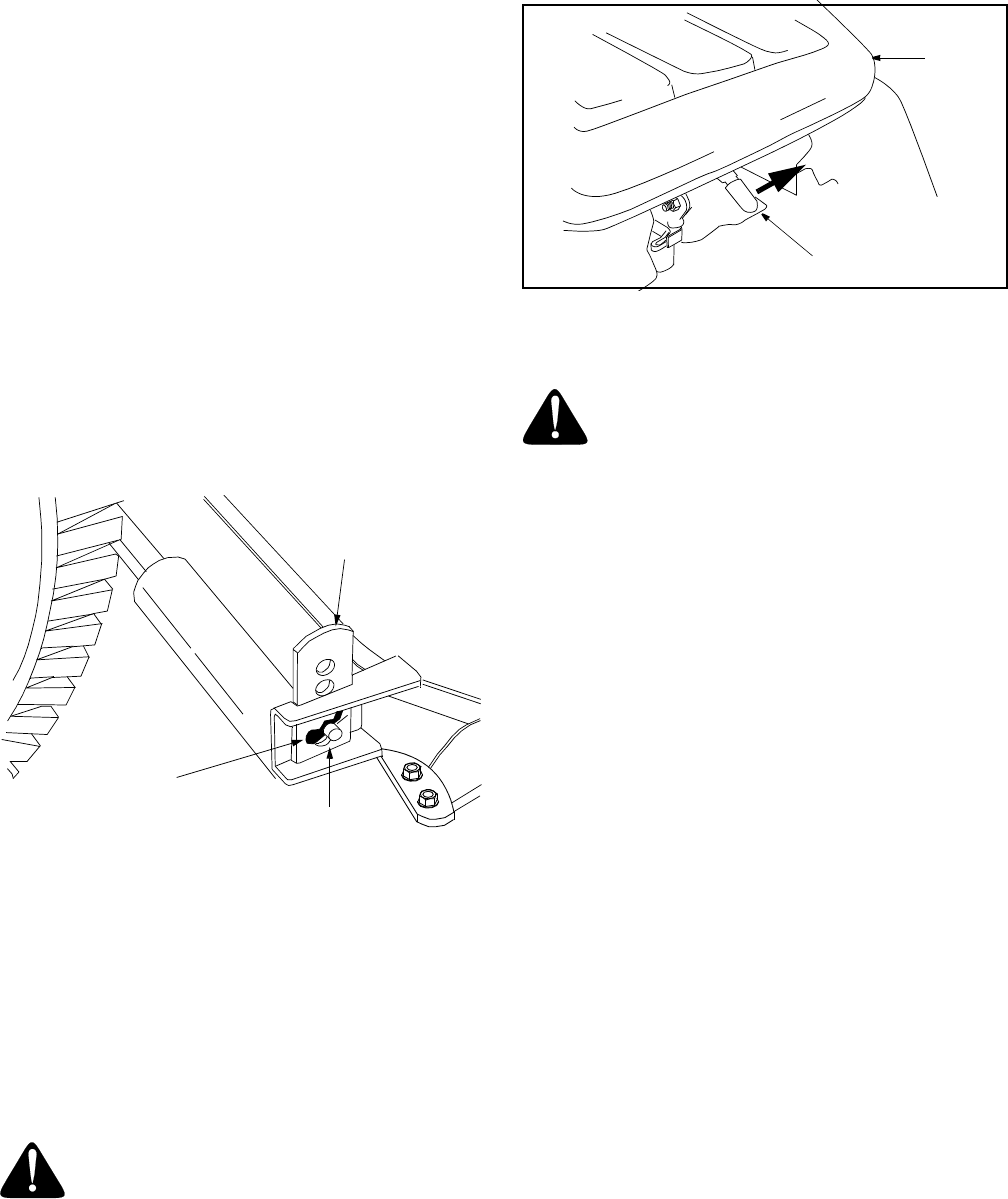
• Remove the clevis pins and hairpin clips from the
deck roller brackets on the left and right sides of the
cutting deck. See Figure 11.
Figure 11
• Position the deck roller brackets up or down
through the slots on the rear of the deck until
desired position is reached, then re-attach with the
clevis pins and hairpin clips just removed. See
Figure 11.
NOTE: Be certain that the left roller bracket and the
right roller bracket are set in the same position.
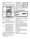
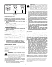
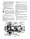
SEAT ADJUSTMENT
WARNING: Before operating this machine,
make sure the seat is engaged in the seat
stop, stand behind the machine and pull back
on seat until fully engaged into stop.
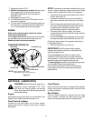
Quick-Adjust Seat
To adjust the position of the seat, move the seat
adjustment lever to the left and slide the seat forward or
rearward. Make sure seat is locked into position before
operating the tractor. See Figure 12.
Figure 12
PARKING BRAKE ADJUSTMENT
Never attempt to adjust the brakes while the
engine is running. Always disengage PTO,
move shift lever into neutral position, stop
engine and remove key to prevent unintended
starting.
If the tractor does not come to a complete stop when the
brake pedal is completely depressed, or if the tractor’s
rear wheels can roll with the parking brake applied, the
brake is in need of adjustment. The brake disc can be
found on the right side of the transmission in the rear of
the tractor. Adjust if necessary as follows:
• Looking at the transmission from the right side of
the tractor, locate the compression spring and
brake disc.
• Loosen, but do NOT remove, the hex nut found on
the right side of the brake assembly.
• Using a feeler gauge, set the gap between the
brake disc and the brake puck at 0.011inches.
• Re-tighten the hex nut loosened earlier.
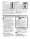
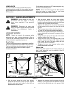
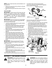
STEERING ADJUSTMENT
If the tractor turns tighter in one direction than the other,
or if the ball joints are being replaced due to damage or
wear, the steering drag links may need to be adjusted.
Adjust the drag links so that equal lengths are threaded
into the ball joint on the left side and the ball joint on the
right side:
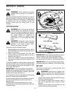
• Loosen the jam nut found on the drag link at the
rear of the ball joint. See Figure 13.
• Remove the hex nut and lock washer on the top of
ball joint. See Figure 13.
• Thread the ball joint toward the jam nut to shorten
the drag link. Thread the ball joint away from the
jam nut to lengthen the drag link.
• Replace hex nut and lock washer and retighten the
jam nut after proper adjustment is achieved.
NOTE: Threading the ball joints too far onto the drag
links will cause the front tires to "toe-in" too far. Proper
toe-in is between 1/16" and 5/16".
Hairpin Clip
Clevis pin
Deck Roller Bracket
Seat
Seat Adjustment Lever