


7
Section 2: Assembly
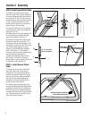
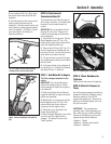
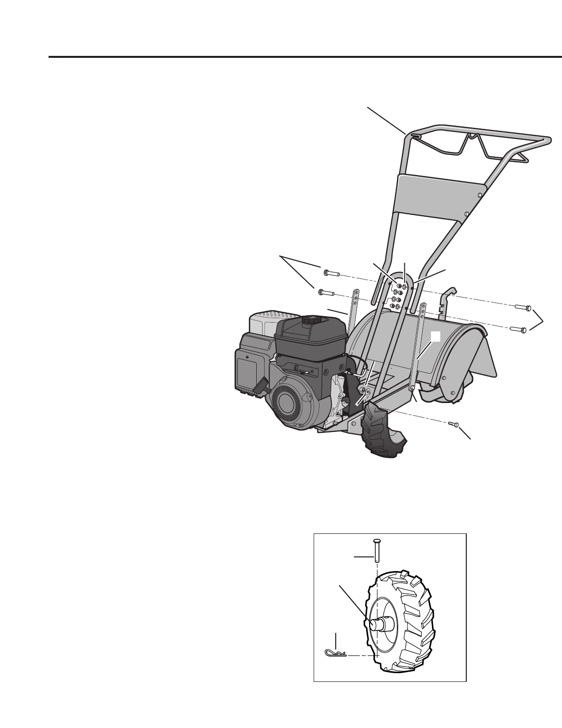
STEP 2: Attach Handlebar
1. Attach the two legs of the handlebar
support (A, Fig. 2-2) loosely to the inner
sides of the tiller frame using two 3/8"-16
x 3/4" hex hd. screws (B), two 3/8” flat
washers (C) and 3/8"-16 hex locknuts (D).
2. Using using two 5/16"-18 x 1-1/2" hex
hd. screws (G), 5/16" split lockwashers
(H) and 5/16"-18 hex nuts (I), loosely
attach the the handlebar support (A) using
the upper holes.
3. There are three height adjustment holes
in the two handlebar support brackets. E
& F, Fig. 2-2). Use a setting that will
position the handlebars at approximately
waist level when the tines are 3”-4” into
the soil. Loosely attach the handlebar
support brackets
to the outside of the
handlebar assembly (K) using two 5/16"-
18 x 1-1/2" screws (G), 5/16" split lock-
washers (H) and 5/16"-18 hex nuts (I).
NOTE: If a support bracket will not move,
loosen attaching screw (J) and nut.
IMPORTANT: The support brackets must
be assembled
to the outside of the
handlebar assembly.
4. Tighten all handlebar mounting
hardware securely.
STEP 3: Move Tiller Off Shipping
Platform
To move the tiller without the engine
running, put the wheels in their
FREEWHEEL position, as described below.
1. Use a sturdy block to raise one wheel
off the ground.
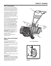
2. Remove the hairpin cotter (L, Fig. 2-3)
and wheel drive pin (M). Slide the wheel
inward on the wheel shaft (N). Reinstall
the wheel drive pin and hairpin cotter
through the wheel shaft only (not through
the wheel hub). Repeat with the other
wheel.
3. Using the handlebar as a lever, roll the
tiller to a flat area.
IMPORTANT: Before starting the engine,
the wheels must be placed in their WHEEL
DRIVE position (pins through wheel hubs
and wheel shaft). This procedure is
described in “Wheel Drive Pins” in
Fig. 2-2: Attach handlebar.
G
H
A
F
E
I
B
C
G
K
J
D
Fig. 2-3: Wheel in FREEWHEELING
position (wheel drive pin through wheel
shaft only).
M
N
L