


Operation (continued)
17
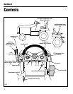
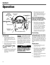
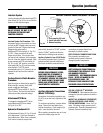
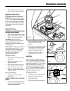
Interlock System
Leaving the seat while the attachment/PTO
drive switch (X, Fig. 6-1) is on or while the
brake is off will stop the engine.
DO NOT OPERATE THE UNIT IF THE
INTERLOCK SYSTEM DOES NOT
FUNCTION PROPERLY.
Interlock System Test Procedure: With
the engine running, stop tractor on a level
surface (do NOT engage brake) and raise
yourself off the seat. Engine should stop.
Engage brake and press the
attachment/PTO drive switch (X, Fig. 6-1)
to “ON”. Raise yourself off the seat.
Engine should stop. If the engine does
not stop in both instances, do not operate
the unit. Have the interlock repaired. With
engine running and PTO drive switch (X,
Fig. 6-1) in the “ON” position, move the
travel pedal (M, Fig. 6-1) into the reverse
travel position. The PTO should
automatically shut off. If it doesn’t, do not
operate the unit and have the interlock
repaired.
Perform Electric Clutch Break-in
Procedure
Start the engine as instructed on page 16.
With the engine running at full (fast)
speed, engage and disengage
attachment/PTO drive switch (X, Fig. 6-1)
10 to 15 times. Perform this step before
initial use and after extended storage.
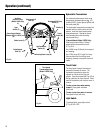
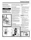
Attachment/PTO Drive
To engage the attachment/PTO drive,
press attachment/PTO drive switch
(X, Fig. 6-1) to “ON”.
Hydraulic Attachment Lift
Pull attachment lift lever (K, Fig. 6-1) back
to lift attachment. Push lever forward to
lower attachment. When lever is released,
it will return to neutral, except when
WARNING
connections to prevent debris from
entering the hydraulic system.
KEEP HYDRAULIC CONNECTIONS CLEAN.
Dirty hydraulic connections can
contaminate the hydraulic fluid and
damage hydraulic components.
DIRTY HYDRAULIC CONNECTIONS CAN
CONTAMINATE THE HYDRAULIC FLUID
AND DAMAGE HYDRAULIC
COMPONENTS. KEEP RUBBER PLUGS IN
PLACE. NEVER USE HANDS TO FEEL
FOR HYDRAULIC LEAKS. HOT
HYDRAULIC FLUID LEAKING AT HIGH
PRESSURE COULD PENETRATE SKIN.
USE ONLY TROY-BILT
®
APPROVED
ATTACHMENTS. Other attachments could
damage the hydraulic system and void the
warranty.
INSPECT ALL HYDRAULIC COMPONENTS
FOR HIGH PRESSURE LEAKS BEFORE
TESTING OR REPAIRING. Never “feel” for
leaks. Oil leaking at high pressure could
penetrate skin. Operating temperatures of
hydraulic fluids are extremely high.
WARNING
pushed fully forward to “FLOAT” position.
Use the “FLOAT” position to allow the
attachment to follow ground contours.
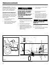
Auxiliary Hydraulic Lever (20 HP Units):
Pull auxiliary hydraulic lever (L) back to
activate auxiliary hydraulic attachment.
Push lever forward to reverse direction.
BEFORE USING HYDRAULIC LEVERS,
MAKE SURE THE ATTACHMENT IS
COMPLETELY HOOKED UP. MOVE
ATTACHMENT THROUGH THE COMPLETE
LIFT RANGE SLOWLY TO MAKE SURE
THERE IS NO INTERFERENCE. MAKE
ADJUSTMENTS IF NECESSARY.
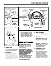
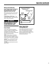
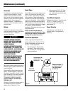
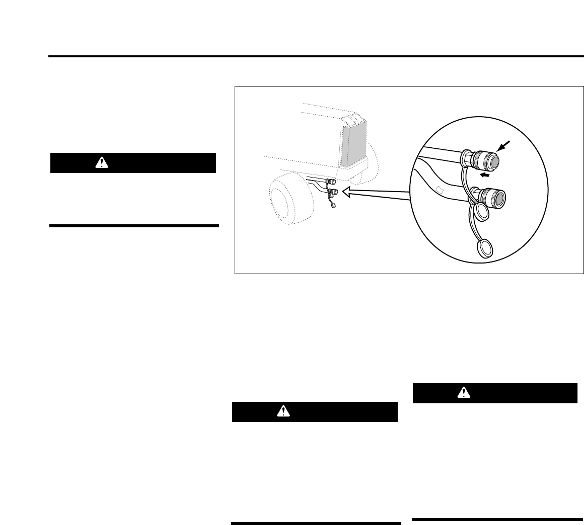
Auxiliary Hydraulic Connections
(Model 13076 Only)
Connections for auxiliary hydraulics (see
Fig. 6-2) are on the front, right-side of the
frame.
To use these connections, remove rubber
plugs. Clean all dirt and debris from
around connections. Push coupling (Q)
back. Insert hydraulic hose end.
When auxiliary connections are not in use,
secure the rubber plugs over the
WARNING
1. Push coupling (Q) back.
2. Install hydraulic hose end.
3. Release coupling.
Q
Fig. 6-2
AUXILIARY HYDRAULIC CONNECTIONS (MODEL 13076 ONLY)