


7PV
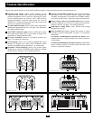
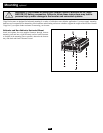
• Connect DC Wiring:
Connection to Two DC Terminals
PV1000HF and
PV1800HF models
include two DC termi-
nals; PV3000HF models
include four DC terminals
(two positive and two
negative). For PV3000HF
models, it is acceptable to
use only one set of cables
to connect your battery to
only one positive and one
negative DC terminal,
however, your PV3000HF may provide
reduced output power. It doesn’t make a
difference which positive and negative
terminal you choose for the connection
because both positive terminals are internally
bonded and both negative terminals are also
internally bonded.
Regardless of the model, you must run posi-
tive cable(s) through user-supplied UL-listed
fuse(s) and fuse block(s) of the proper size:
PV1000HF—175 amp fuse, PV1800HF—
250 amp fuse, PV3000HF—500 amp fuse.
See Specifications page for Minimum Recommended Cable Sizing
Chart. An excellent source of cables are battery jumper cables.
Output performance will decrease if you use only one jumper cable.
Connection to Four DC Terminals
To obtain maximum
output power from
PV3000HF models, it is
recommended (but not
required) that you use
four 00 gauge cables to
connect your battery to all four DC
terminals. In this connection you must run
two positive cables of equal length through
two user-supplied UL-listed 250-amp fuses
and fuse blocks. Use the equivalent of two
00 cables in all other connections within the
battery system.
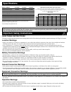
Length & Gauge of Cables
Although your Inverter is a high-efficiency
converter of electricity, its rated output
capacity is limited by the length and gauge
of the cabling running from the battery to
the unit. Use the shortest length and largest
diameter cabling (maximum 00 gauge) to fit
your Inverter’s DC Input terminals. Shorter
and heavier gauge cabling reduces DC volt-
age drop and allows for maximum transfer
of current. Your Inverter is capable of deliv-
ering peak wattage at up to 200% of its rated
continuous wattage output instantaneously.
See Specifications page for details. Heavier
gauge cabling should be used when continu-
ously operating heavy draw equipment
under these conditions. Tighten your
Inverter and battery terminals to approxi-
mately 3.5 Newton-meters (2.58 foot lbs.) of
torque to create an efficient
connection and to prevent excessive heating
at this connection. Insufficient tightening of
the terminals could void your warranty.
• Connect Ground: Using a #8 AWG wire
or larger, directly connect the Main Ground
Lug to the vehicle's chassis ground or earth
ground. See Feature Identification section to
locate Main Ground Lug. All installations
must comply with national and local codes
and ordinances.
• Connect Fuse: In addition to the
protection provided by the Inverter’s
internal fuses, NEC article 551 requires that
you connect your Inverter’s positive DC
Terminal(s) directly to a UL-listed fuse(s)
and fuse block(s) within 18 inches of the
battery. See diagrams below for proper fuse
placement.
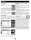
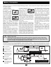
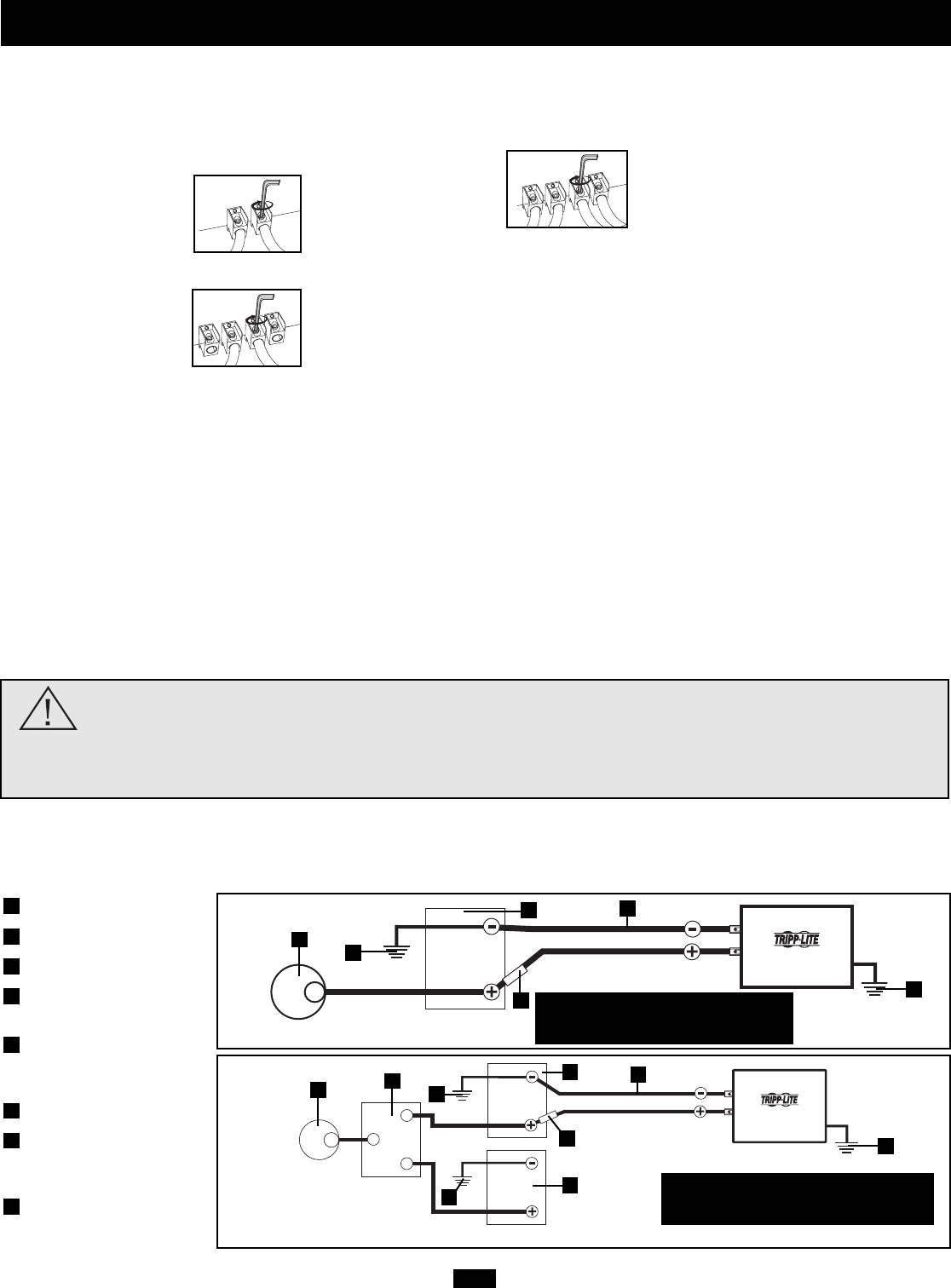
Battery Connection
Vehicular
Your Inverter’s Nominal DC Input Voltage must match the voltage of your battery or batteries—12 Volts in most vehicular applications. It is possible
to connect your Inverter to the main battery within your vehicle’s electrical system. In many vehicular contexts, the Inverter will be connected
to one or more dedicated auxiliary (house) batteries which are isolated from the drive system to prevent possible draining of the main battery.
12 Volt Inverter
12 Volts
12 Volts
12 Volt Main Battery Connection—two DC terminals
12 Volt Alternator
Vehicle Battery Ground
12 Volt Main Battery
12 Volt Auxiliary (House)
Battery
UL-Listed Fuses & Fuse
Blocks (mounted within 18
inches of the battery)
Battery Isolator
Large Diameter Cabling,
Maximum 00 Gauge to Fit
Terminals
8 AWG (minimum) Ground
Wire to Vehicle Frame or
Earth Ground
8
7
6
5
4
3
2
1
12 Volt Inverter
12 Volts
12 Volts
12 Volts
12 Volt Main and Auxiliary (House) Battery Connection (Isolated Parallel)—two DC terminals
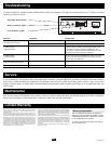
Connect your Inverter to your batteries using the following procedures—always loosely twist each pair of cables (one positive and
one negative) together:
WARNING! Never attempt to operate your Inverter by connecting it directly to output from an alternator rather than
a battery or battery bank.
CAUTION! Observe proper polarity with all DC connections. If polarity is reversed, the Inverter’s 40-amp internal
fuses will blow. To access internal fuses, disconnect all equipment and batteries from the Inverter. Then, unscrew
and remove front panel; slide out bottom panel to access fuses. Replace blown fuses with an equal number of new
fuses of the same type and amperage. Replace front panel and screws.
PV3000HF
Note: Connection to all four DC terminals
is recommended to provide the maximum
output power from PV3000HF models.
Note: Connection to all four DC terminals
is recommended to provide the maximum
output power from PV3000HF models.
PV1000HF
PV1800HF
1
2
3
5
7
8
1
2
2
6
4
3
5
7
8
PV3000HF