


12V DC
CAUTION!
Observe proper polarity. Reversed polarity
will blow internal fuses. See manual.
3PV
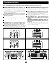
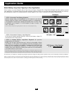
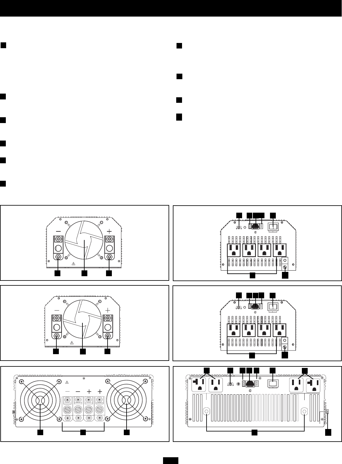
Feature Identification
Identify the premium features on your specific model and quickly locate instructions on how to maximize their use.
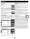
Operating Mode Switch: controls Inverter operation. Set this
3-position rocker switch to “ON” to have your Inverter provide
connected equipment with AC power by converting DC power
from an attached battery. Set switch to “OFF” when not using
connected equipment to prevent battery drain. Set switch to
“REMOTE” to remotely monitor and control the Inverter with
the use of an optional remote module.
“LOAD” Indicator Lights: intuitive “traffic light” signals show
approximate equipment load level. See page 4 for instructions
on reading indicator lights.
“BATTERY” Indicator Lights: intuitive “traffic light” signals
show approximate charge level of your battery. See page 4 for
instructions on reading indicator lights.
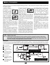
DC Power Terminals: connect to your battery terminals. See
page 7 for connection instructions.
AC Receptacles: allow you to connect equipment that would
normally be plugged into a utility outlet. PV3000HF models
include two receptacles that accept either 15- or 20-amp plugs.
Resettable Circuit Breaker(s): protect your Inverter against
damage due to overload. PV3000HF models include two separate
20-amp circuits. See page 4 for resetting instructions.
Remote Control Module Connector: allows remote monitoring
and control with an optional module (Tripp Lite model
APSRM4, sold separately or included with PV3000HF models).
See remote module owner’s manual for connection instructions.
Battery Charge Conserver (Load Sense) Dial: conserves battery
power by setting the low-load level at which the Inverter auto-
matically shuts off. See page 4 for setting instructions.
Multi-Speed Cooling Fan(s): quiet, efficient fans prolong
equipment service life.
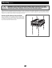
Main Ground Lug: properly grounds the Inverter to vehicle
grounding system or earth ground. See page 7 for connection
instructions.
Low Battery Alarm/Shutdown (internal, not shown): auto-
matically detects low voltage and shuts down Inverter to preserve
vehicle battery.
Overload Alarm/Shutdown (internal, not shown): automatically
detects wattage overload on Inverter outlets and shuts down
Inverter as a protective measure.
1
2
3
4
5
6
7
8
9
PV3000HF Rear Panel PV3000HF Front Panel
10
GROUND
HI
MED
LOW
LOW
MED
HI
REMOTE
REMOTE
OFF
ON
LOAD
SENSE
GREATER
LOAD
ON
LESSER
LOAD
ON
BATTERY
LOAD
20A
15A
15A
20A
OUTPUT
CIRCUIT
BREAKER
20A
OUTPUT
CIRCUIT
BREAKER
20A
12V DC
CAUTION!
Observe proper polarity. Reversed polarity
will blow internal fuses. See manual.
PV1800HF Rear Panel PV1800HF Front Panel
HI
MED
LOW
LOW
MED
HI
REMOTE
BATTERY
LOAD
REMOTE
OFF
ON
LOAD
SENSE
GREATER
LOAD
ON
LESSER
LOAD
ON
GROUND
12V DC
CAUTION!
Observe proper polarity. Reversed polarity
will blow internal fuses. See manual.
PV1000HF Rear Panel
PV1000HF Front Panel
1
2
73
8
5
10
6
99 4
1
2
73
8
10
5
9
4
4
9
4
4
HI
MED
LOW
LOW
MED
HI
REMOTE
BATTERY
LOAD
REMOTE
OFF
ON
LOAD
SENSE
GREATER
LOAD
ON
LESSER
LOAD
ON
GROUND
1
2
73
8
10
5
5