


MODEL NUMBER: PV1000HF PV1800HF PV3000HF
Continuous Power (@ 20° C):* 1000 Watts 1800 Watts 3000 Watts
Double Boost™ Peak Surge Power:* 2000 Watts 3600 Watts 6000 Watts
DC Input Volts (Nominal): 12 VDC 12 VDC 12 VDC
DC Input Voltage Range: 10 - 15 VDC 10 - 15 VDC 10.5 - 15 VDC
DC Input Connection:
User Supplied Cables User Supplied Cables User Supplied Cables
Output Volts (Nominal): 120 VAC 120 VAC 120 VAC
Output Frequency (Nominal): 60 Hz, ± 0.5% 60 Hz, ± 0.5% 60 Hz, ± 0.5%
Efficiency: Up to 94% Up to 94% Up to 94%
Output Waveform:
Modified Sine Wave Modified Sine Wave Modified Sine Wave
* DoubleBoost duration (instantaneous). Actual output depends on battery age, battery charge
level and ambient temperature. The policy of Tripp Lite is one of continuous improvement.
Specifications are subject to change without notice.
This product designed and engineered in the USA.
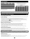
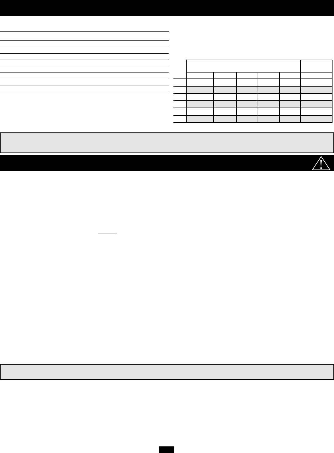
Wire Gauge
2 Conductors 4 Conductors
(all models) (PV3000HF only)
Watts 6 4 2 0 00 Twin 00
500 15 ft 25 ft 39 ft 62 ft 79 ft 158 ft
700 11 ft 18 ft 28 ft 44 ft 56 ft 112 ft
1000 N/R 12 ft 20 ft 31 ft 39 ft 78 ft
2000 N/R N/R N/R 16 ft 20 ft 40 ft
2400 N/R N/R N/R 13 ft 16 ft 32 ft
3000 N/R N/R N/R 10 ft 13 ft 26 ft
†N/R = Not Recommended. NOTE: Acceptable power is directly related to cable length (i.e. - the shorter the cable, the better the performance)
Important Safety Instructions
SAVE THESE INSTRUCTIONS!
This manual contains important instructions and warnings that should be followed during the installation, operation and storage of all Tripp Lite Inverters.
Location Warnings
• Install your Inverter in a location or compartment in your vehicle that minimizes exposure to heat, dust, direct sunlight and moisture.
Flooding the unit with water will cause it to short circuit and could cause personal injury due to electric shock.
• Leave a minimum of 2" clearance at front and back of the Inverter for proper ventilation. To avoid overheating the Inverter, any
compartment that contains the Inverter must be properly ventilated with adequate outside air flow. The heavier the load of connected
equipment, the more heat will be generated by the unit.
• Do not install the Inverter directly near magnetic storage media, as this may result in data corruption.
• Do not install near flammable materials, fuel or chemicals.
Battery Connection Warnings
• Multiple battery systems must be comprised of batteries of identical voltage, age, amp-hour capacity and type.
• Because explosive hydrogen gas can accumulate near batteries if they are not kept well ventilated, your batteries should not be
installed in a “dead air” compartment. Ideally, any compartment would have some ventilation to outside air.
• Sparks may result during final battery connection. Always observe proper polarity as batteries are connected.
• Do not allow objects to contact the DC input terminals. Do not short or bridge these terminals together. Serious personal injury
or property damage could result.
Ground Connection Warnings
• Safe operation requires connecting the Inverter's Main Ground Lug directly to the frame of the vehicle or earth ground.
• For protection against possible electrical shock hazards, if the Inverter is operated in wet or damp conditions, a user-supplied, portable
GFCI (ground fault circuit interruptor) must be connected between each Inverter receptacle and the equipment it powers.
Equipment Connection Warnings
• Do not use a Tripp Lite Inverter in life support or healthcare applications where a malfunction or failure of a Tripp Lite
Inverter could cause failure of, or significantly alter the performance of, a life support device or medical equipment.
• You may experience uneven performance results if you connect a surge suppressor, line conditioner or UPS system to the output of
the Inverter.
Operation Warnings
• Your Inverter does not require routine maintenance.
• Potentially lethal voltages exist within the Inverter as long as the battery supply is connected. During any service work, the battery
supply should therefore be disconnected.
• Do not connect or disconnect batteries while the Inverter is operating from the battery supply. Dangerous arcing may result.
2PV
Specifications
Minimum Recommended Cable Sizing Chart
†
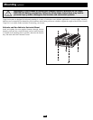
Always loosely twist each pair of cables (one positive and one negative) together.
Use in conjunction with DC wiring connection instructions in the Battery Connection section.
Using 4 conductors is recommended (but not required) to obtain
maximum output power from PV3000HF models.
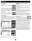
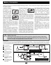
Tripp Lite Inverters include a Battery Charge Conserver (Load Sense) Control which saves battery power by allowing users to
set the minimum load level at which the unit’s inverter turns on. Users can significantly reduce the No Load DC Input Current to
a very low amperage power level with the use of this control.