


5
Configuration
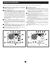
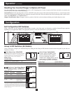
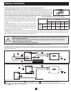
Set Configuration DIP Switches
Using a small tool, set the Configuration DIP Switches (located on the front panel, see diagram) to optimize Inverter/Charger operation
depending on your application. Refer to the appropriate section to review the instructions for your specific model.
INPUT C/B 10A
OUTPUT C/B 12A
B4 B3 B2 B1
A4 A3 A2 A1
Group B Dip Switches
Group A Dip Switches
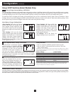
Group A DIP Switches (All Models)
Usingasmalltool,configureyourInverter/ChargerbysettingthefourGroupADIPSwitches(locatedonthefrontpanelofyourunit;see
diagram) as follows:
A2
Operation
(continued)
Resetting Your Inverter/Charger to Restore AC Power
YourInverter/ChargermayceasesupplyingACpowerorDCchargingpowerinordertoprotectitselffromoverloadortoprotectyour
electrical system. To restore normal functioning:
Overload Reset:Switchoperatingmodeswitchto“DCOFF”andremovesomeoftheconnectedelectricalload(i.e.,turnoffsomeofthe
AC devices drawing power which may have caused the overload of the unit). Wait one minute, then switch operating mode switch back to
either“AUTO/REMOTE”or“CHARGEONLY.”
Output Circuit Breaker Reset: If tripped, remove a portion of the load, wait one minute and then press breaker button to reset.
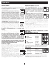
Select Low AC Input Voltage Point for
Switching to Battery—OPTIONAL*
Voltage and Level
120V Models 230V Models Switch Position
A105V 201V A4Up&A3Up
B95V 182V A4Up&A3Down
C85V 163V A4Down&A3Up
D75V 144V A4Down&A3Down
(factory setting)
A1A2A3A4
A1A2A3A4
A1A2A3A4
A1A2A3A4
A3
A4
A1
* Most of your connected appliances and equipment will perform adequately when your
Inverter/Charger's Low AC Voltage Input Point (DIP Switch #3 and #4 of Group A) are set
to Level B (95V for 120V Models/182V for 230V Models). However, if the unit frequently
switches to battery power due to momentary low line voltage swings that would have little
effect on equipment operation, you may wish to adjust this setting. By decreasing the Low
AC Voltage Input Point, you will reduce the number of times that your unit switches to
battery due to voltage swings.
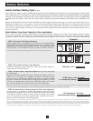
Select Battery Type—REQUIRED
CAUTION: The Battery Type DIP Switch setting must match
the type of batteries you connect, or your batteries may be
degraded or damaged over an extended period of time. See
"Battery Selection" section for more information.
Battery Type
Switch Position
AGM/GelCell(Sealed)Battery Up
WetCell(Vented)Battery Down(factorysetting)
Select Charger Enable/Inhibit
SwitchispresettoENABLE,which
permits continuous battery charging.
If you are connecting your unit to
batteries with a separate charger, you may
setthisswitchtoINHIBITtodisableits
built-in charger to prevent overcharging.
Battery Type Switch Position
Inhibit Up
Enable Down(factorysetting)
A1A2A3A4
A1A2A3A4
ENABLE
INHIBIT
Level A
Level B
Level C
Level D